|
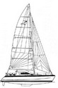
St Francis |
|

PLUMBING SYSTEMS
|
Engine Driven Water Maker |
Water Catchment & Filtration |
|
Deck Shower and Washdown |
Jabsco SensorMax 17 Pump Repair |
Last Updated: 01/25/2026
If you are a CSY owner, here's a link to the Plumbing page from our CSY days. CSY Plumbing Page
Fresh Water Tankage - General Comments
On our last boat, a CSY 44 (monohull), we had 165 gallons of fresh water in 5 tanks, but if I could chose an ideal water tankage it would be around 250 gallons in 3 tanks. At 165 gallons, using about 7 gals per day for the two of us, we could go for 20-25 days without a refill. With 250 gals we could go 35 days, a big difference which would allow us to make any of the worlds normal long ocean passages without a refill.
One of the compromises with choosing a light-weight catamaran is the smaller water tankage. On our cat, we have one water tank in each hull, just above the keel. Though the manufacturer's claim is 80 U.S. gallons per side, when we actually measured the capacity, by filling from measured 19 liter bottles, we found the tank full at 218 liters or 57.5 gallons. Quite a difference from the Sales Brochure!
However, we quit worrying about tankage when we added a water maker to our boat.
Water Catchment
"Tell me more about rain water collection while cruising. What do you do with it after it enters the boat? Does it get filtered? Do you put directly into your water tanks?"
Our catamaran has a large "roof" over the cockpit, and it was built with water catchment in mind. When we catch water, we first let it rain for about 10 minutes and maybe do a bit of swabbing down if the top is dirty. Then we just put the built-in hoses into one of several 5 gallon utility buckets we have aboard. By the time the buckets are full, the water is clean enough to put the hoses directly into the tank fills.
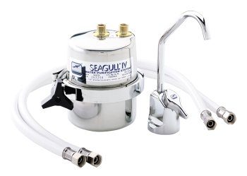
Our pressure water system has a 20 micron filter before the galley feed, and a Sea Gull IV filter on a separate tap used only for drinking water.
Deck Shower and Wash down
We have a have a deck shower on the aft deck with a quarter turn shut off valve, and use a kitchen spray nozzle for the working end. We use about 15' of hose so that we can rinse the dinghy, flush the outboards and wash down spills on the aft deck and cockpit if needed. I've been using that now for 10 years.
In tropical out-island cruising situations, we take all of our showers on the back deck--it's cooler out there! In anchorages and marinas, we shower below.
For pressure salt water wash down at the bow--for a muddy anchor, I use a coiled 25' hose attached to a pressure salt water circuit in a bow locker. High pressure SW at the bow is a must for those muddy anchorages. I still see people trying to clean up the anchor, chain and deck with a bucket and brush.
Engine Driven Water Maker
On our monohull, after going through 2 12v watermakers with low output rates and fairly high current consumption, we finally did a DIY installation of a 40 gallons per hour water maker that cost half the price of the cheapest commercial version of that capacity. See details of that project on our CSY Plumbing Systems page.
On the catamaran, the previous owner had (using info from our CSY design) already 80% installed an engine-driven watermaker. But it had never been fully commissioned. We have since finished the install and commissioning.
The high pressure (HP) pump is belted to the port main engine. It is mounted on a stainless steel plate welded to a longitudinal shaft mounted over the front of the engine through the forward engine room bulkhead.
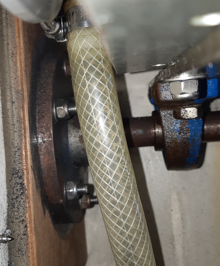
Flange for Pump attached to fwd bulkhead
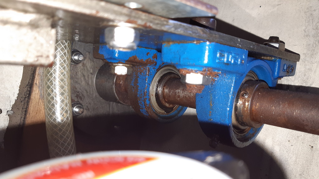
Steel plate on rotating bearings mounted on the flange is what holds the pump assembly
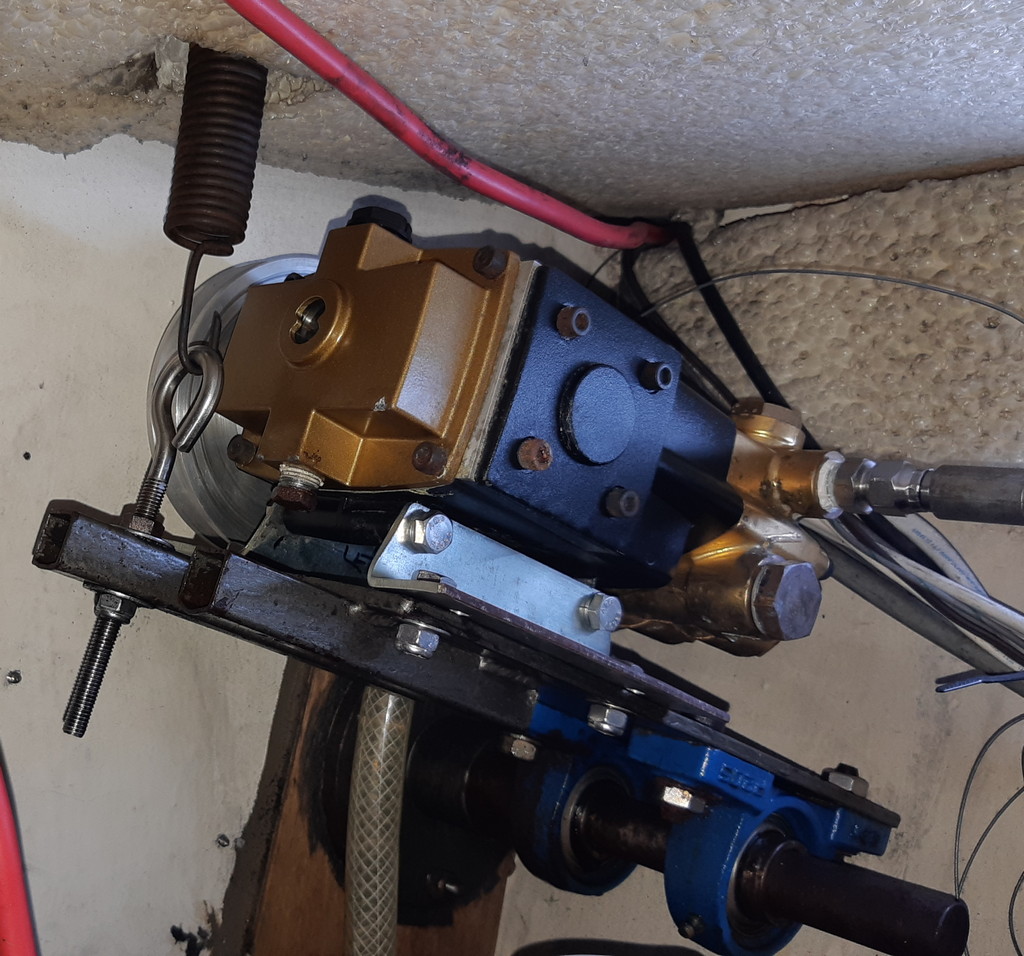
Pump assembly rotates on the flange mounted to the fwd bulkhead.

Side view of pump assembly (no belt in place yet)
When not in use, the belt is removed and the pump assembly is rotated up and held out of the way by a piece of line. To install the belt, the line is removed and the spring attached to the eyebolt as shown in the pictures above, and the belt attached around the pulley. The spring acts as a tensioner to keep the assembly in place.
The membrane tubes are under the seat just outboard of the forward port bunk.
The two filters and Jabsco Water Puppy boost pump are in the aft inboard cabinet in the forward port head.
The raw water inlet is taken off the port forward head inlet.
Based on 10 years of use with my similar installation on our previous boat we believe mechanically-driven is a better solution (than electrically-driven), and certainly less expensive.
Also see our Presentation on Making Our Own Watermaker
Why Engine Driven. I've used a small (6 gallons an hour) 12 volt water maker previously, and it was a real pain running it daily or for hours at a time to keep up with our 6-7 gallon a day usage. Besides that, it needed 17 amps per hour to make its 6 gallons of water.
Some more modern units make about a gallon of water for each amp hour used, but they are very expensive and not easily owner-repairable in the field.
Several years ago I saw two home-built units using a commercial HP plunger pump run off the main engine and two of the large membranes producing about 40 gallons an hour. These were each built for around $2K. A similar store-bought unit would cost around $8K and a kit unit about $5K.
So for a savings of up to $6K, and in order to learn more about these systems, I decided to build my own mechanically driven unit. Mine is powered by the main engine since we don't use a generator, but it could also be powered by a generator or an AC motor of about 1.5-2 HP. DC motors aren't available that large, so are not an option. For many reasons I stayed away from using electronic/automatic control systems, except the electric boost pump, and used only reliable mechanically operated components.
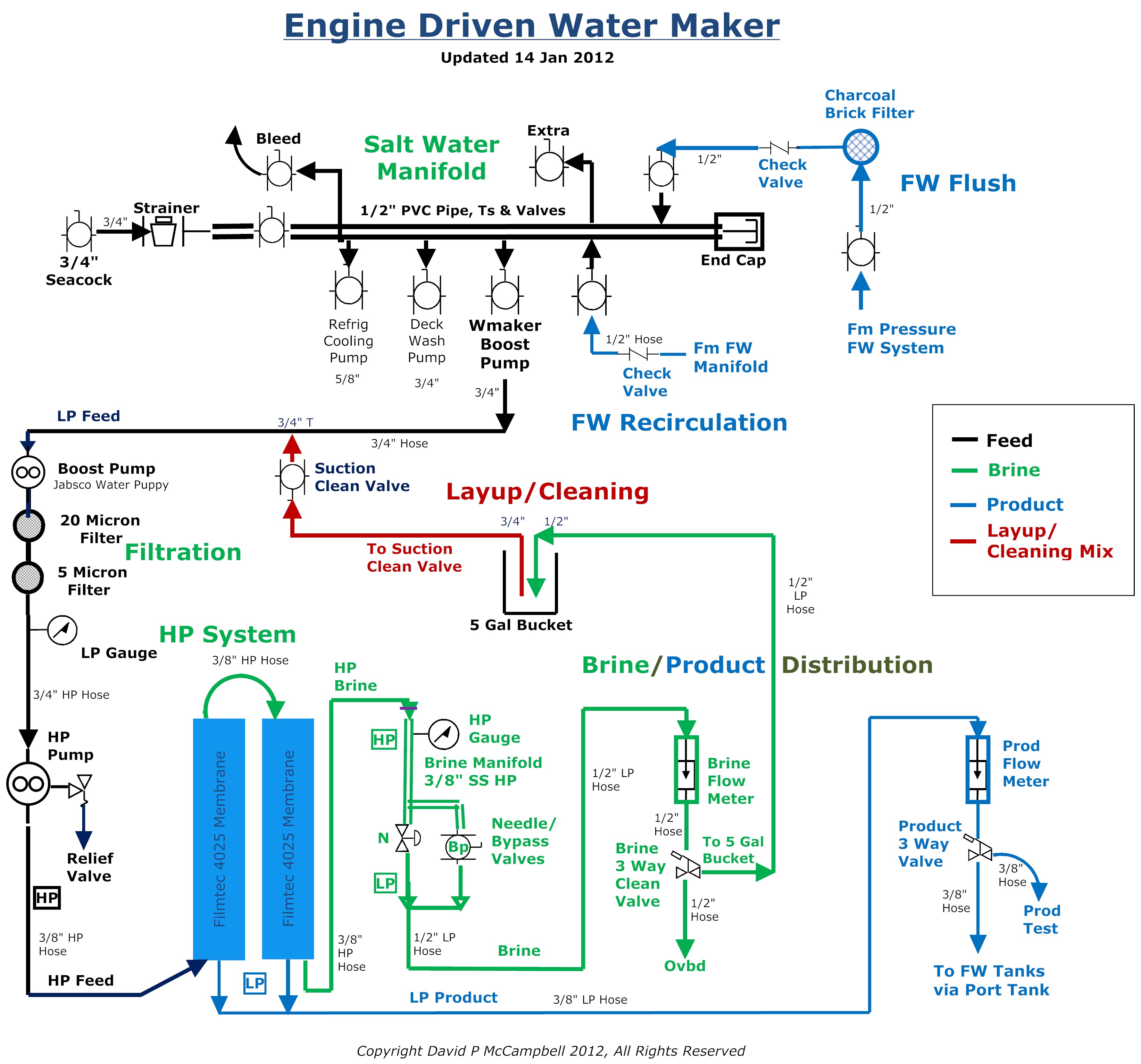
The System Diagram. Above is the diagram of my entire system with all the components shown. (Click on picture to enlarge) There are many ways to lay out a water maker system and different opinions as to what is needed and what is nice to have. I've looked at lots of water maker system diagrams, talked to most of the manufacturers and discussed the fine points with many owners.
While building my system, I stayed away from electronics and automatic systems/sensors because of extra expense, complexity and the high failure rate of electronics in a hot engine room. Also, a lightning strike would certainly kill a system with electronics. So my system is all manually controlled and monitored, since I will be onboard and actively running the system while it is operating.
Equipment Options. Here are my opinions on some of the options available when buying/building a water maker system. These ideas are based on what I have read and discussed with many knowledgeable water maker people.
-
I think both LP and HP pressure gages and brine and product flow meters are necessary for accurate and safe system monitoring. Flow rates and pressures are critical to reliability and long life of the membranes. I bought Dwyer all plastic and SS flow meters and all SS oil filled gages.
-
A good pressure relief valve is necessary for safety when operating the HP portion of the system. I originally used a relief/regulating valve with a bypass feature made for a pressure cleaning gun because it came with my original used pump from a friend. As only the relief valve feature is needed and in order to reduce complexity I have since bought a small brass relief valve and set to pop off pressure to 1000 PSI.
-
Product water distribution and quality can easily be controlled manually with a 3 way valve and portable salinity meter. No need for electronic monitoring here. I can test the product water with my handheld salinity meter or by taste.
-
A boost pump is necessary to maintain positive pressure going into the HP pump no matter where the HP pump is mounted.
-
Fresh water flushing of the system for about 5 minutes is necessary after each use in order to reduce corrosion. This can easily be manually controlled through valves. Again no need for an automatic/electronic system.
-
And finally. cleaning and lay up solutions can be easily mixed and introduced into the system through the use of valves and a 5 gallon bucket. The bucket is also useful for product water waste and testing.
The High Pressure Pump. Cat, Giant, HyPro and several others make good plunger pumps that can be used for a water maker system. I originally installed a two plunger Grainger Teel 2P414D (made by Hypro as a 2230B-P) mainly because it was available used at a good price from a friend. It turned out to be barely adequate for our 40 GPH system.
Because I wanted better flow for good scouring and to ensure full output from the membranes I have since installed a 3 plunger pump (the Hypro 2345B-P, rated at 4.7 GPM but really producing 5 GPM, about $325 new on the internet at www.deindustrial.com June 2008). This also allows me to retain the smaller pump with the same mounting foot print as a backup. (note: as of 2010, deindustrial is out of business, see our Watermaker Links for updated source).
Rather than using a very expensive Stainless Steel or Titanium head HP pump I am using significantly less expensive but entirely suitable bronze head pumps. I am told by several experienced dealers that these should be good for at least 1000 hours of use before the high pressure pulsations with salt water might damage the pump head. At 40 gals an hour that's 40,000 gallons I can make before I can expect the risk of a pump head failure. At 10 gallons a day usage that is about 11 years of use if I use RO water every day. We won't be using RO water every day and there will be at least a couple of months a year when the system will be in layup while we are away from the boat on travel. Given the cost differential, roughly $300 for a bronze head and $1500 for a SS head I am using bronze.
The pump pulley has been sized to allow the pump to run at 1725 RPM when the engine is running at 2200 RPM. The pump will produce its maximum output at that RPM and the engine is comfortable under way at 2200 RPM or at anchor at a little lower RPM. Since the big pump can produce the full rated 42 GPH through the membranes at about 700 PSI I can run the engine at less RPM if needed and still produce the full rating of product water by simply raising the pressure setting a bit. I have accurately calibrated my engine tachometer and can monitor the engine and HP pump speeds with my handheld electronic tach.
Rather than use an electromagnetic clutch to control the on/off switching of the HP pump I decided to use a manual system with a custom-built SS vertically sliding tray for the pump under the engine front pulley sheave. This decision was based on the following:
-
There is not much room in my engine room for a EM clutch,
-
It is electric and a constantly rotating part, therefore another point of failure
-
AquaMarine, Inc, a vendor of water maker kits, has told their customers that the smaller sizes under about 6 inches are unreliable. Since my engine sheave is 6" I would want a smaller pump sheave size.
It is a relatively simple matter to raise the pump up to attach the belt to the single engine sheave. By pushing lightly down on the pump and locking it in place with wing nuts the belt tension can be set as needed. This setup produces a fool proof, non electric, no-spares-required system.
Operating Calculations
In water maker literature some flow specs are given in GPH and others in GPM, so convert when necessary by dividing GPH by 60 to get GPM.
The feed input is the sum of the brine and product outputs, since all the water coming in goes to either product or brine. The product output divided by the feed input gives the recovery rate.
With the original smaller HP pump, under operating conditions I planned to run the unit at 1725 RPM, 825 PSI, 2.5 GPM brine output and 40 GPH product output. That assumed I would have 3.2 GPM or 190GPH input from the HP pump to work with. It is rated at 3.0 GPM but really produces 3.2 GPM.
I arrived at these operating parameters by calculating the maximum recovery rate I could make while remaining within Filmtech specifications for long membrane life (max 1000 PSI, each 2540 membrane 21 GPH product flow). The max recovery rate for each 40 inch membrane is 13 percent, so for two membranes in parallel you get 26 percent. A better figure to use without stressing the membranes over the long term is 11 percent each, 22 percent total.
The calculations are as follows.
40 GPH product output divided by 190 GPH feed input (40 GPH product plus 150 GPH brine outputs) gives 20.6 percent recovery, well within specs.
In order to maintain proper scouring/flushing of the membranes at least 2 GPM feed flow is needed, with 4 GPM being much better for long term use. So for the small pump 3.2 GPM (2.5 GPM brine plus .67 GPM product outputs) is OK. For the larger pump, 5 GPM is much better.
Based on the above, and my own testing at different pressures. I could run the system with the small pump up to 850 PSI and make 43 GPH at 22.2 percent recovery, but that is just above the max I've seen recommended for long term use. Filmtech says the max operating pressure for their membranes is 1000 PSI. 825 PSI is slightly below the recommended max and and well below Filmtech's max, and it still produces almost as much fresh water (40 GPH) as running it at 850 PSI. The Jabsco boost pump runs at about 8 PSI while the system is operating, providing adequate positive pressure against the HP pump head.
Layup and Cleaning the Watermaker
The lay up solution (2 tbsp sodium metabisulfite per gallon of water) is sucked out of a 5 gallon bucket through the manifold cleaning system valve as shown on the diagram. The same system is used for the two cleaning solutions. If you start with the system fresh water flushed and full of fresh water, I calculated the system holds about 2.5 gallons of water when all the lines, pumps, membranes and filters are full. Therefore, with the bucket about half full, any mix should be calculated for about 5 gallons.
Regarding cleaning solutions, I've been advised to be fastidious about keeping the membranes clean, away from any petroleum or chlorine products and flush after every use rather than rely on cleaning products to clean the membranes. The membranes can only take a couple of cleanings before they will be permanently damaged and exhibit degraded output.
Additional Info Resources. The original source for much of my inspiration came from another boater, RutuOnline (now defunct). Rutu built his own system using similar components to mine, but with much more in the way of automatic/electronic control systems. His description of how he selected components similar to mine was excellent. However, this site is no longer active. I have recently found another site here: Leo Lichtveld's site.
A second very helpful source is the AquaMarine, Inc website. AquaMarine sells do-it-yourself kits, also using similar components. Both have good detail on equipment choices and installation tips. AquaMarine has a great installation and operating manual, a copy of which might be obtained from another Aquamarine owner.
Also, there are numerous commercial water maker sellers that have websites and handout material of some usefulness. See here for more links to watermaker info and parts suppliers.
Below is a list of the major parts I used and some pictures of the water maker project under construction and as installed on Soggy Paws.
Major parts list:
-Hypro 2345B-P rated at 4.7 GPH
source
-Mount for HP Pump-Custom Stainless Steel by Local Welding Shop
-Boost Pump-Jabsco Water Puppy
18660-121, 12 Volt, rated at 6 GPM, 3/4" Fittings
source
-Pressure Vessels-2 ea, Codeline Model 25M100, 40 inch
source
-Membranes-2 ea, Filmtec SW30-2540 source
-Pressure Relief/Regulating Valve-General Pump ZKSR, adjustable relief
setting
-Water Filter Housings-3 ea, Clear (don't use Pollenex), 3/4" Fittings
-Water Filters-20 Micron Paper, 5 Micron Paper, Charcoal Brick
-Flow Meters-Dwyer, Brine 0-5 GPM, Product 0-60 GPH
-Pressure Gauges-all SS Case/Fitts Oil Filled, HP 0-1400 PSI, LP -30 to +70 PSI
-Needle Regulating Valve-Dragon, SS 1000 PSI (Dragon #10M-053 or McMaster
#4644K33)
-Better option is Grainger's adjustable brass pop off valve
-Bypass Valve-Quarter Turn, SS 1000 PSI
-3 Way Valves with 1/2" Fittings-2 ea, Grey Plastic (SMC)
source
-Hose and Fittings-HP 3/8" hose/fitts, 1/2" SS manifold; LP 3/8", 1/2" and 3/4"
hose/fitts
-Strainer-3/4" Fittings
-Salt Water Manifold-misc 1/2" PVC Pipe, Fittings and Valves
-Mounts-Misc sizes of 3/4" varnished wood to suit, grey plastic pipe hangars
-Salinity Test Meter-Hanna Handheld TDS Meter
-Electronic Tachometer-Neiko Digital Tachometer
Jabsco SensorMax 17 Fresh Water Pump Repair
We struggled for a year trying to find the leak in our water system that was causing the pump to "cycle" about once a minute. (and the fresh water system to lose pressure over time if the pump was turned off).
We visually (and with hands) leak-checked the entire system, tightened all the connections, rebuilt the pumps with vendor-supplied rebuild kits, etc. Could not stop the "leak". Finally a friend clued us in to what was likely the cause and a simple fix.

Jabsco SensorMax 31750 Parts Diagram
If pump is losing pressure and cycling periodically without any visible leaking in piping or connections do the following:
-
Disconnect electrical wiring and plumbing from pump
-
Remove pump from bulkhead, 4 screws
-
Remove gold plastic cover over pressure sensor, 1 screw
-
Remove black plastic housing, 2 screws, including pressure sensor, over non-return valve chamber
-
Lift edge of non-return rubber diaphragm carefully with small screw driver
-
Look underneath for any foreign particles stuck on housing or diaphragm
-
If so, use small, wide pliers to grab diaphragm edge and carefully pull it off
-
Clean diaphragm and plastic underneath so it will make good seal (ours had white power encrustation, causing the leak).
-
Cover diaphragm lightly with silicone
-
Replace diaphragm by pushing bottom firmly back into housing
-
Replace all parts and reinstall pump
Copyright 2026
WebDesignsInternational