|
CSY |
|

|
Home Page |
||
|
CSY Workshop Home |
||
|
Soggy Paws CSY Home |
||
|
New Cat Workshop Pages |
||
|
Engine |
||
|
Electrical Systems |
||
|
Plumbing
Systems |
||
|
Refrigeration |
||
|
Rig
& Sails |
||
|
Hull |
||
|
Cockpit |
||
|
Deck |
||
|
Interior |
||
|
Steering |
||
|
Electronics |
||
|
Computers |
||
|
Workshop Links |
||
|
Miscellaneous |
||
|
About Us |
||
|
Contact Us |
||
|
About CSY Boats |
||
|
See more 'boat project' discussions by Dave on the CSY Owners Forum |
STEERING
| Monitor Wind Vane | CPT Autopilot - Trouble Shooting and Repair |
| Self Steering | Rudder Post Pillow Bearing |
| Rudder Repairs | RayMarine 5000 CPT Mod |
Last Updated: May 1, 2017
Future Additions:
-Raymarine 5000/CPT Head Replacement-completed pics
-Raymarine 1000 Autopilot for Backup
(CSY
Owners Association Post 14 Oct 08) For what it's worth,
like Craig, I also filled my rudder with epoxy after finding a crack in 1999
around the post at the top of the rudder. However, there was no movement of
the rudder around the post. I added some high strength silica to the mix and
poured it in the top after grinding a trough around the post, a little at a
time with a slow catalyst. I dropped the rudder in 2005 to have a look and
it was fine then as it is now 9 years and 10K miles later. I do keep a close
eye on it, though.
Not sure it was the ultimate fix, but like Craig's fix, it seems to have
worked. If you are not headed off shore any time soon you might go with what
you have as a fix and see how it does. You can always redo it later, and
contrary to popular belief, there are capable yards and technicians out here
in the third world. Or spend the money now, over $2K in the US I believe,
and have a new one made.
(CSY
Owners Association Post 16 Oct 08) Great, a lively debate on something important. It's
a good thing that we have all agreed to disagree in this forum. And I
respect opinion regarding building new rather than repairing these rudders.
That is often the best course of action, especially with things like old
stainless (chain plates, tangs and such).
But despite argument to the contrary, I still believe that Craig's and my
fix for OUR rudders was adequate. I agree that building a new rudder, if
properly engineered, is a good fix. Before repairing my rudder I first
assumed that Peter Schmitt did his job in engineering the basic strength of
the rudder by sizing the parts correctly. Since most are still intact after
30 years and there is no SS involved, I think that that is a good
assumption. As I see it, the goal is to prevent the fiberglass blade from
rotating on the shaft. I don't think adhesion of the internal material to
the rudder stock or flat bar will help that much. Rather it's the bronze
flat bars that will do that if they are tightly imbedded in the internal
material whatever that is. I made sure that mine were, with no wiggle (a
good engineering term) before or after the fix. Although not mentioned on my
previous post, I did spend a good amount of time flushing and drying the
interior. With the rudder off the boat it was easy to turn it upside
down to facilitate flushing. I think that any critters left inside
made no difference and just added to the internal material. The bronze
should be fine even with a bit of moisture inside. That's why bronze
was used instead of SS.
At least 3 of us and maybe more are convinced that this type of fix works
well if the internals are intact. As proof we have at least two rudders with
more than 9 years and many thousands of miles on them after repair. I'll be
checking mine every haulout. You'll be the first to know and this
forum second, if I find a problem.
Re Sonny's rudder, only he can make the final decision on what to do for his
situation. Since he has movement around his post, and if he's planning on
crossing an ocean soon, he may want to do something different than we did. I
would. I don't know what a "rudder guru" is in his case, but there are
many naval architects that could probably give him an educated opinion for a
small fee. Peter is probably not available for consultation. Since our
advice is free it may not be worth as much, but at least it gives him some
data points for what others have done. It would be interesting to know if
anyone has had a problem with any repaired or rebuilt rudder.
Since we are heading north to Costa Rica today I won't have internet while
we are putting a few more miles on our rudder. But maybe others who have
done rudder repairs will want to voice their opinion in the mean time.
That's what this forum is for. I don't think that you can ever have too many
opinions, and they are all worth considering.
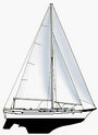
Self Steering
(2006)Since steering is such an important part of passage making and
a circumnavigation, we have multiple ways to steer our boat. We hand
steer only when necessary, like when docking, mooring to a buoy, anchoring
or in close quarters such as entering a narrow channel. The rest of
the time one of our 3 self steering systems does the work.
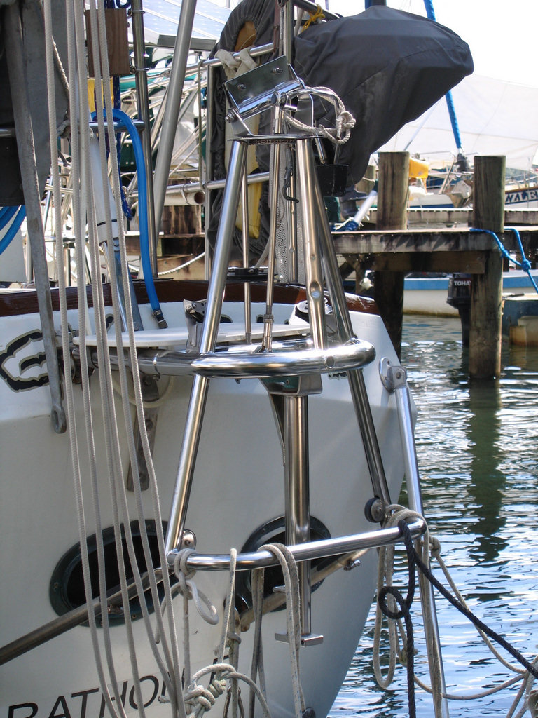
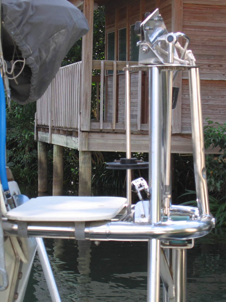
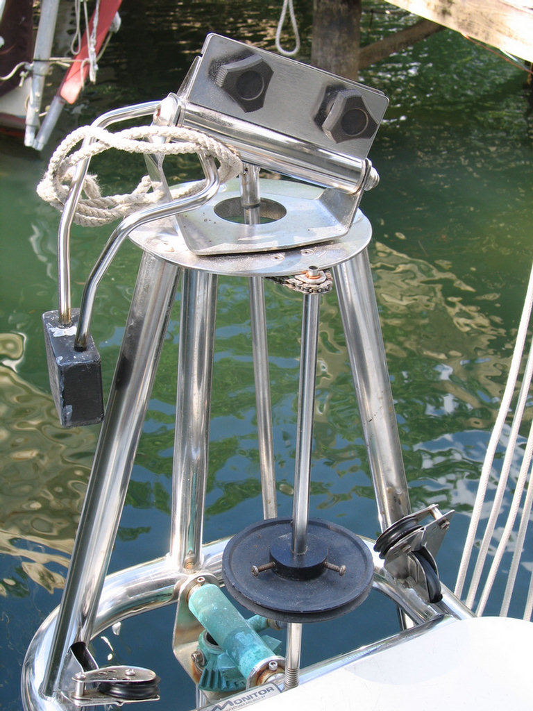
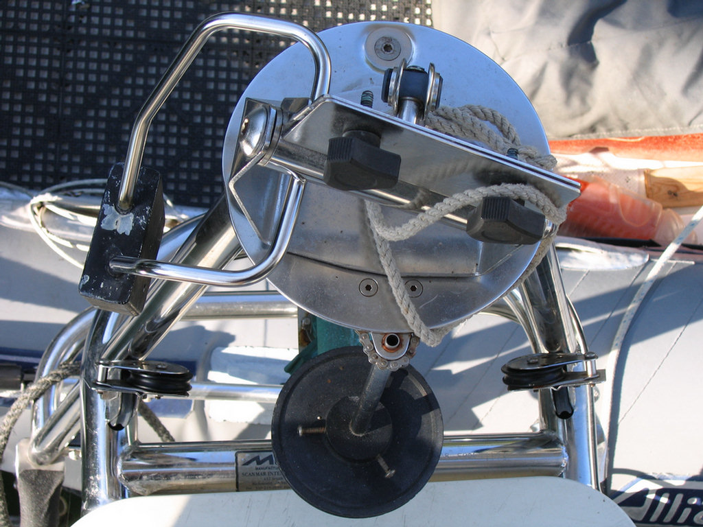
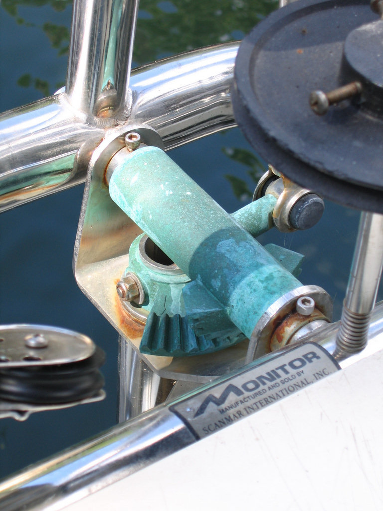
Our Monitor wind vane, is used for longer passages, and can only be used when the dinghy is stowed forward on the cabin top. It is extremely powerful and can handle the boat in almost any conditions except very light or no wind. One of its big advantages is that it uses no electricity. It's disadvantage is it takes some time to set up. See further down this page for more details and pictures of the Monitor.
Most of the time and during times when there is very light or no wind, a wheel mounted CPT autopilot is used. It has steered the boat on a 4 year trip around the Carribbean and up and down the Florida Keys countless times during six years of Boy Scout charters. Its big advantage is that it is very quick to set up and easy to use, but it does use roughly one amp of 12 volt power per hour. We carry three complete units plus multiple spare parts aboard just in case there is a problem. See details below under the section on the CPT Autopilot.
We can also use a small push pull Raymarine 1000+ to drive the Monitor on a compass course when needed. It uses very little 12 volt power and drives the steering through the powerful wind vane. If we want to drive a compass course this is the strongest system we have. It can steer the boat in any conditions from no wind through a gale. We have it aboard but have yet to operate it.
A good link for reading up on self steering, and wind vanes in
particular, is Scanmar Marine at:
http://www.Selfsteer.com
This is one of the more important equipment decisions you will make for your
boat so do your homework carefully before you buy.
The Monitor is a servo-pendulum vane. It is less cumbersome, less vulnerable, easier to install and more powerful than wind vanes which use other principles.
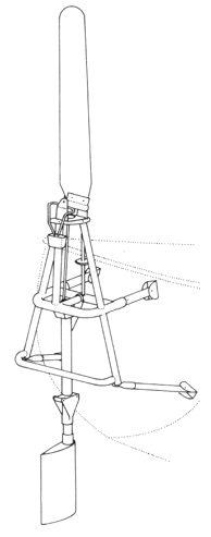 The servo-pendulum system is the most popular principle
for wind vanes in use today. It works well on surprisingly large
yachts since it steers using the boat's own rudder. The more wind
there is, the faster the boat will move through the water, and more
steering power is developed by the servo-pendulum gear. On difficult
points of sail and in harsh weather this is a very welcome
attribute.
The servo-pendulum system is the most popular principle
for wind vanes in use today. It works well on surprisingly large
yachts since it steers using the boat's own rudder. The more wind
there is, the faster the boat will move through the water, and more
steering power is developed by the servo-pendulum gear. On difficult
points of sail and in harsh weather this is a very welcome
attribute.
Another benefit of the Monitor is positive yaw dampening found only with this sort
of gear. As the boat is coming back on course, the water paddle
automatically 'feathers' itself back to neutral position,
eliminating over steering common to some wind vanes.
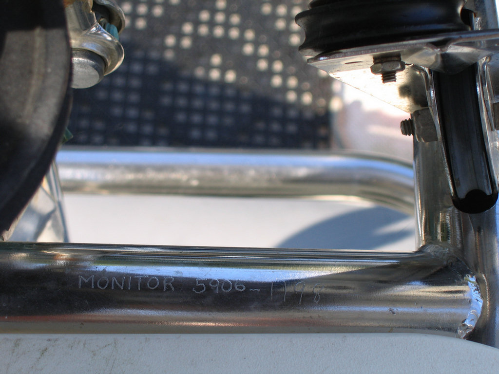
(Jan 2008) Here's some info for anyone interested in purchasing a used Monitor. I've had two of them. The first one was one of the early 80's Larwick models made of all 304 SS. The one I have now is a late 98 Monitor made of all 316 SS. It has all the important upgrades including additional teeth on the gears and the lower tubes support bar which all were added in the mid to late 90s. Larwick sold the company to Scanmar Marine in Ca in the early 80s. Scanmar is the same company that bought the CPT Autopilot company in the late 90s. To determine which unit you may be looking at, look for the date on the forward horizontal support tube beside the Monitor sticker and the word Monitor. Mine reads "Monitor 5906 1198. The 5906 is the serial number, 1198 is Nov 98. They changed to all 316 SS sometime in late 97.
I paid $1800 for mine in 2005 with spares and a wheel mount. The wheel mount is $400 new and the entire unit runs close to $4000 new now. The price of SS has gone way up. A friend bought a 2001 at about the same time for $2000. I've seen them on SSCA for $1500-2000 in the past couple of years.
There is lots of detail on the Monitors at Scanmar's website, including the parts breakdown I believe. Google Scanmar Marine or Monitor Windvane. If the unit you are looking at is in mint condition and a 98 or newer I would say it is now worth $2000 or a bit more. But if it is earlier, I would offer more like $1500-1700 depending on the date and which upgrades it has. If it is a 97 call or email Scanmar with the serial number to find out which SS it was made with.
|
|
|
|
|
|
|
|
|
(CSY
Owners Association
Post - 14 Jan 08) Like most things with a boat an autopilot is a
compromise. Your choice will depend on what you want the AP to do, and how
much money you can spend on it. If it is intended to drive during reasonable
wind/sea conditions and you have a wind vane for heavy conditions then a
lesser AP, preferably one that you can repair yourself, will do fine. Heavy
blue water conditions require a first class AP like the W-H or a strong wind
vane or both. The trade offs here are that a strong AP will require lots of
amp hours to run and the wind vane will not. However, the vane requires wind
and the AP does not. There is a work around for the vane in no wind
conditions using a small tiller pilot to drive the vane.
If money is not a problem and you want one of the best for all conditions
buy a W-H like Jim Dill did. It is made by a small company that only builds
autopilots and is highly recommended by Steve Dashew and other serious blue water
cruisers. It also has earned high ratings in the SSCA Cruising Equipment
Surveys. There are
also others with good reputations, and you can find the names and
recommendations by looking at previous posts on this forum. The subject has
been pretty well covered in the past.
I chose a CPT autopilot because I have learned to fix it myself with commonly
available electronic parts, it was inexpensive compared to others, it does a
reasonable job steering the boat in moderate conditions, and I have a
Monitor wind vane for heavy conditions. I've had it steering our boat for 10
years now, and it has done a 4 year trip around the Caribbean and 80 charter
trips up and down the Fla Keys. However, the company is now out of business,
and the units are only available used, often for less than $100 and mostly
from dissatisfied owners who can't fix them when there is a problem.
Obviously the CPT is not for everyone, but for us it is perfect.
(CSY
Owners Association Post - 2007) Like many of you reading
this, I have a CPT Autopilot II. Since purchase about 9 years and 10K miles
ago it has worked adequately steering my boat (CSY 44 walkthrough cutter,
40K lbs) 90 percent of the time while cruising. I'm not sure I would trust
it in really heavy going, so I have a Monitor wind vane for that. The two
back each other up in most conditions. The CPT drove all the way around the
Caribbean during a 4 year trip and about 75 trips up and down the Florida
Keys in light to moderate conditions while we did not use the Monitor at
all. We will use the Monitor for future ocean crossings, but will still use
the CPT for light wind and motoring conditions. I like the CPT for its
strength, repairability, and low amp draw (less than 50 amp hours a day if
the boat is balanced). I also like being able to see what is going on with
the unit in the cockpit instead of it being hidden under the aft bunk. As
mentioned elsewhere it is absolutely waterproof and should be kept that way
if the boxes are opened up.
Initially, during installation I found that the compass unit had to be
placed off the binnacle about 3 feet away on the cockpit combing in order to
work smoothly with the drive unit. Also, the belt needed a constant
tensioning device in order to keep it from slipping when under load. This I
fashioned out of two small pieces of aluminum plate bolted together with
three small machine screws. It is held in place with a loop of bungee cord
in order to pinch the belt together in the middle and provide even tension
around both pulleys. While steering the CPT still leaves somewhat of a
sinuous wake in some conditions, but the more balanced the boat and more you
work with the two controls the better it gets. I consider the steering
adequate and probably about as good as I could do.
In the Spring of 2006, after our trip around the Caribbean and during my
sixth year of Boy Scout charters up and down the Florida Keys I began to
notice some erratic behavior. It would intermittently have trouble
maintaining a straight course. Then by early Summer it had begun to
occasionally steer a hard over circle to the left without any warning.
Finally it would no longer steer the boat running the drive motor/pulley to
port whenever I moved the compass dial in either direction off the center
null position. At that point I took over the helm and let the scouts earn
their keep and do all the steering for the last few trips.
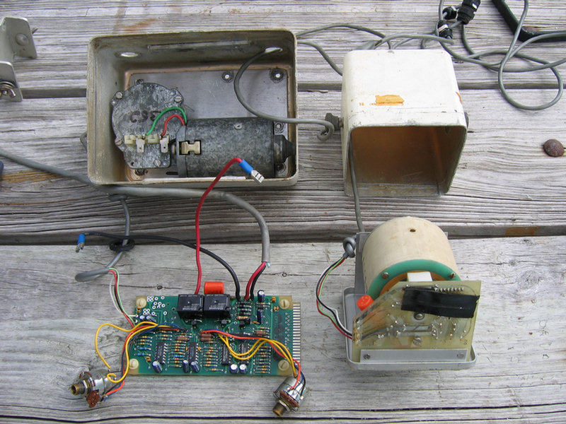
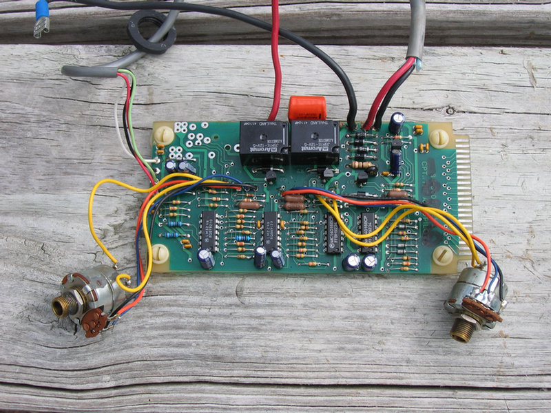
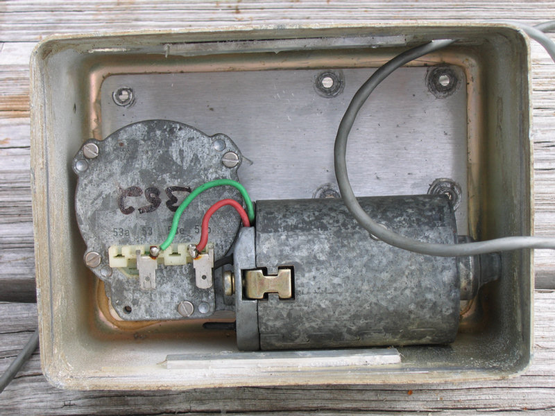
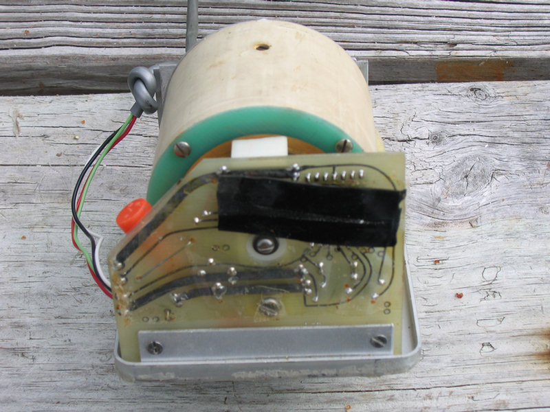
After the Summer charter season was over I spent time checking all the external wiring and connections in the hope of finding some simple solution. There was none. I checked the internet for any mention of CPT and problems with it. There is a good bit written about problems owners are having with the unit and with Scanmar but no actual repair information. So I opened both the drive and compass unit boxes and carefully inspected the circuit boards and wiring connections for obvious problems with a head mounted magnifying glasses. I found none. Finally I enlisted the help of a friend, Wes Whitley, who had extensive electronics trouble shooting experience. Here's what we found and what we did about it:
1 I now have parts from 4 different units-two pre 1990 (Autopilot-one serial number 3309 the other not available) and two about 1997 (Autopilot II-serial numbers 14150 and 14267). One I bought new in 1997, the others have either been given to me by frustrated owners or I have bought for less than $100 after mine started acting up. I have recently acquired a working fifth unit (Autopilot II-serial number 14378, newer than all the others) for $40 here on the Rio Dulce. It was just too good a deal to pass up and gives me two version II working spares for our circumnavigation.
2 A close examination of the two circuit boards in each unit and the compass itself reveals that there were only minor component changes, mainly manufacturer, over those years. All the components on the circuit boards are off the shelf parts readily available through parts houses such as Digi-Key (digikey.com, 800-344-4539) for very little money. The boards are large enough that anyone with a fine soldering iron, a solder sucker, good eyes and a little soldering skill would have no trouble replacing bad components. I consider this a real plus for someone going offshore or to third world countries with an autopilot or any other piece of electronic equipment. The main problem with trouble shooting this unit is that there is no circuit diagram available. Even so we were able to fix our problems with just basic trouble shooting techniques. So that I can get going in a hurry again if a unit should stop working, I now have both the drive and compass units wired with short leads to easily accessible terminal boards. They can be quickly replaced with the spares while underway with a minimum of work.
3 The drive unit was sold with two different motors but the same circuit board and case. Sometime in the 1990s CPT began using a 24 volt Bosch motor instead of the older 12 volt motor. The newer unit with the 24 volt motor has a II behind the Autopilot name. All the circuit boards in the drive units were identical in the way they fed 12 volts to the motors. According to Bosch feeding 12 volts to a 24 volt motor allows it to develop more torque and therefore become a more powerful unit. If you want a spare, the 24 volt motors, PN 0390257693, with gearing attached are still available for about $100 each. Call Mike Juliano at Bosch in Texas at 972-625-1075/1. He would love to get rid of the 40 or so he has on the shelf, made specially for Scanmar. So far, I have been unable to find anyone with a circuit diagram, and Scanmar, the current owner of CPT is unwilling to provide a copy or even discuss trouble shooting as mentioned in previous posts on Sailnet.com and other lists. BTW the rights to CPT are for sale from Scanmar if anyone is interested in becoming the world distributor/repair facility for CPT. There are 14,000 plus units out there and from what I've read from frustrated owners it might be a good business.
4 In order to bench test the various components of each unit we cut the 4 wire cable between the drive and compass units on each, set them on a work bench and provided 12 volts to each drive unit while alternately connecting up different combinations of compass and drive units. By rotating the compass dial clockwise and counter clockwise we could easily see which units had problems and which did not.
5 In order to get the units open I had to first remove the black plastic trim around the rim of the boxes, then carefully use a sharp long thin knife (like a long blade box cutter) to cut the silicone caulk between the outer case and the aluminum face plate. It is necessary to cut the caulk about a half inch in from the front of the face plate. The corners are the most difficult but with perseverance and a narrow blade, after all is cut the faceplate can be gently pulled out by the knobs and rocking the faceplate back and forth.
6 My original unit, new in 1997, serial number 14267, had several problems. The main problem was that the drive unit circuit board relays had finally worn their points, after about 10 K miles, so that they were too badly pitted to supply current to the motor. They are small black plastic sealed boxes about an inch square with five soldered connections on the bottom each. After removing and replacing both I cut the top off both boxes. The relay that drove the unit to starboard had very badly pitted points and could no longer carry current. The other was not quite as bad but in marginal condition. Their cost was $1.42 each through Digi-Key. It took about a half hour to replace them. The other problem was a loose capacitor found by touching each component on the circuit board in turn with the unit on and in the null position. When we moved this particular capacitor the unit activated intermittently. Inspecting the solder connections with a strong magnifying lens revealed a loose, solder starved connection. This was a two minute fix. We also checked the diodes and 4 IC chips for loose connections and found none. As a precaution against future problems we went ahead and replaced the 4 IC chips. I purchased all the replacement components and several of each for spares as listed in 8 below from Digi-Key.
7 Since we were already inside the boxes, we also took the time to heat and cool each component separately, a common trouble shooting technique, to see if there were any problems temperature extremes would cause. There were none. As mentioned above, replacing any of these components is easy, if you have the component, proper tools and a little soldering skill. Taking the various components apart including the compass unit and its numerous gears and contacts is also not hard, but does requires keeping track of how they will go back together. The hardest part is getting the boxes open and resealed properly.
8 One of my older units when given to me was "not working, couldn't hold a course and was a piece of trash" according to the previous owner. It turned out to only have a bad compass; the 12 volt motor and two circuit boards were in perfect working order. After taking apart the compass itself I found that the oil inside had become somewhat more viscous so that the needle was very slow to follow a course change and sometimes even hung up completely. I could probably be easily fixed by replacing the oil with mineral/compass oil. This may be a class problem with pre 1990s units as the oil ages or the unit bakes in the hot sun. I keep both my units covered with Sunbrella and under the dodger extension. The compass unit circuit board was working well when we tested it with another compass. I have not been able to find the source for the compass itself as there are no markings on it. That would be an interesting project for someone with good internet search skills or who knows the original owner of the company, Charles Pukit.
9 The
parts I ordered through Digi-Key were as follows:
-255-1240-ND Relay Auto Mini SPDT 15A 12VDC $1.42 ea used 2
-296-7030-ND IC Quad Op Amp 14-Dip $.55 ea used 2
-296-2036-5-ND IC Quad Bilateral Switch 14-Dip $.48 ea used 2
-P1187-ND Capacitor Elect 10uf 35V SU Bi-Polar $.15 ea used 1
As mentioned previously just about anything on the circuit boards is
available through Digi-Key, which might very well have been CPT's original
source.
Another example of a CPT repair comes from a friend who had a problem with
his CPT and found that one of the diodes on the drive unit circuit board had
gone bad. He tested all of the diodes in the circuit board and replaced the
one that had a problem. Here are his notes to me: "With regard to your
CPT, our backup CPT would only go in one direction, too. What I did was to
check all the diodes and I found one which was bad. It had the same LOW
resistance in both directions. I replaced it and the unit appears to work
fine. Use the low resistance setting on your volt-ohm meter and measure the
resistance in both directions (i.e. reverse your + and - leads) across each
diode. If one measures low, or very high, in both directions, it may be the
culprit". He also replaced his motor just for drill by "removing all the
bolts from the back of the box including the three around the main shaft and
then prying the motor on the plate away from the back of the box".
All my CPT Autopilot II units use the Bosch
24 volt motor. CPT shifted to the 24 volt motor in the 1990s. Older, pre
early 1990s units used a 12 volt motor. All the units feed the motors 12
volts and need 12 volts coming in. Mike at Bosch in Texas, where I bought a
spare motor several years ago, told me that a 24 volt motor works better
(more torque?) than a 12 volt motor being fed 12 volts and that is why CPT
made the change in motors. Maybe some electrical engineer among us can
explain that.
I have a remote for my CPT but have never used it. I should break it out and
try it.
My experience with the unit over the past 12 years is that it is entirely
adequate in reasonable conditions. And we are now in Ecuador having used it
all the way here. I like having the unit in the cockpit where I can see what
is going on with it, and knowing that I can replace it quickly with a spare
if there is a problem.
I hope that this information helps someone with their CPT autopilot. It
really is a decent unit, and because it can be easily repaired with standard
components, should be considered by serious cruisers going abroad that want
to be able to repair their own gear.
Below find some pictures of an open older unit showing the various
components. The size and accessibility of the electronic components,
simple wiring and straightforward disassembly make testing and repairs easy.
The layout and components are the same as the newer units, only the motor
has changed.
|
|
|
|
|
|
|
|
|
|
|
|
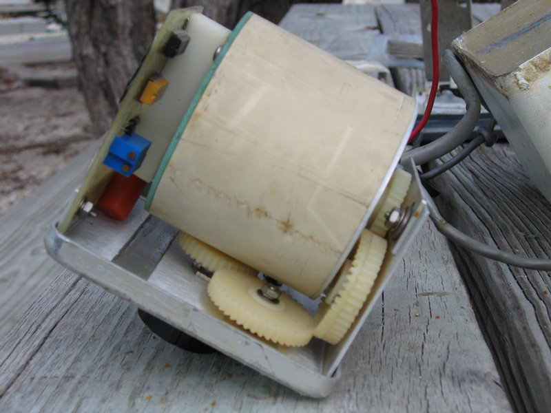
 Belt on the drive unit to the wheel |
 Home-made belt-tensioner mechanism |
|
Make SURE you seal everything up well after you open
up the unit. It's waterproof-ness was one of the original
selling points. Charles Pukit used to sell his units at boat
shows by having one submerged in water and still working. Salt
water and salt air get EVERYWHERE when at sea, so even if your
cockpit is relatively dry, you need to have your electronics fully
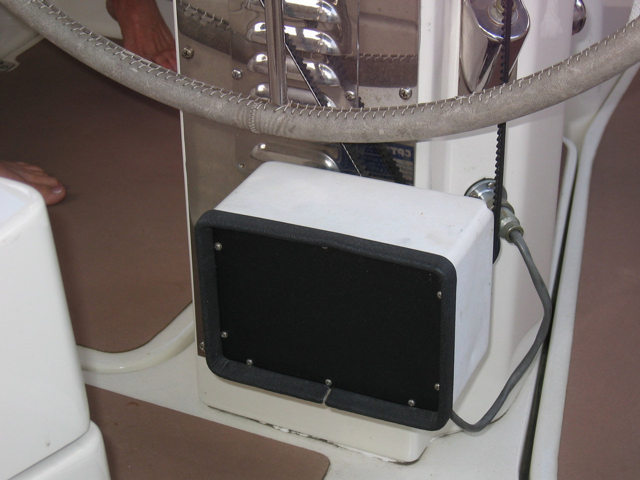
waterproof. 2014 Update: Our CPT Autopilot II has now steered us all the way from Florida, through the Panama Canal, down to Easter Island, through the entire South Pacific, and up through the NW Pacific to the Philippines. 7 Years and about 30,000 miles. It is in use 95% of the time we are underway. It steers well enough and draws little enough, that we often just don't bother rigging up the wind vane. I have "hot swapped" a malfunctioning unit out a couple of times on passage, and I have changed out the relays twice (always later, at anchor in calm conditions--the benefit of having spares you can pop in place while underway). Meanwhile, friends left and right coming across the Pacific were Fed-Exing off their expensive newer electronic units for replacement or repair (both at quite high expense). That's one reason we never switched to the Raymarine setup we show below. |
|


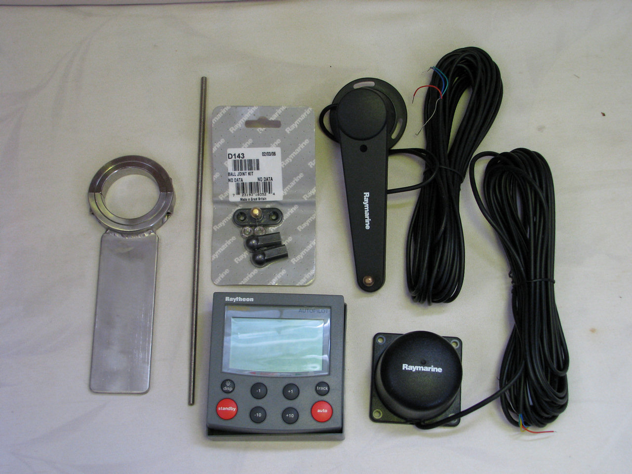
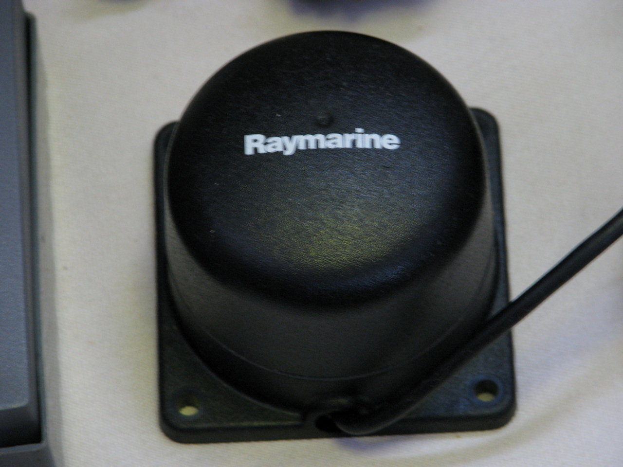
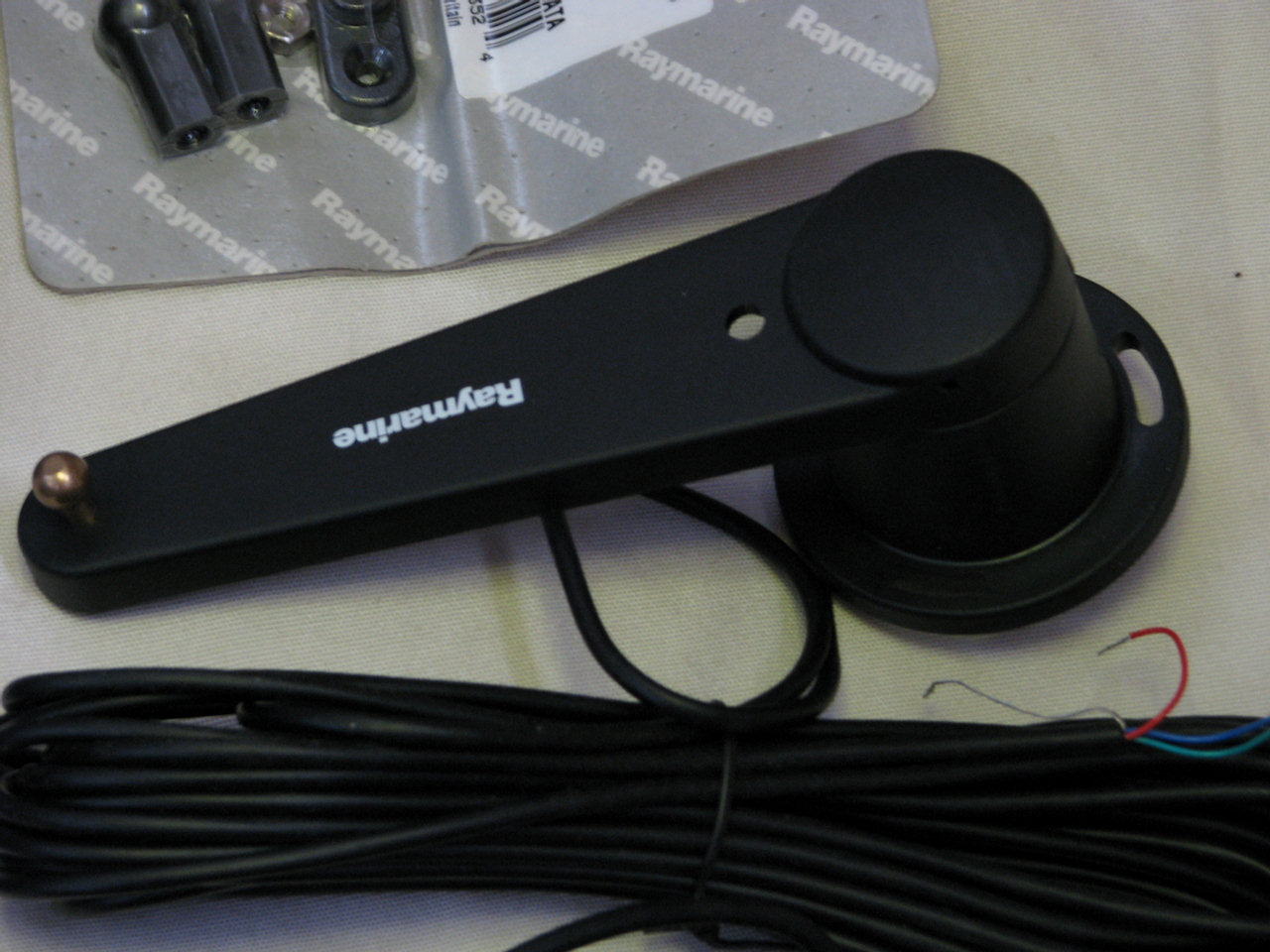
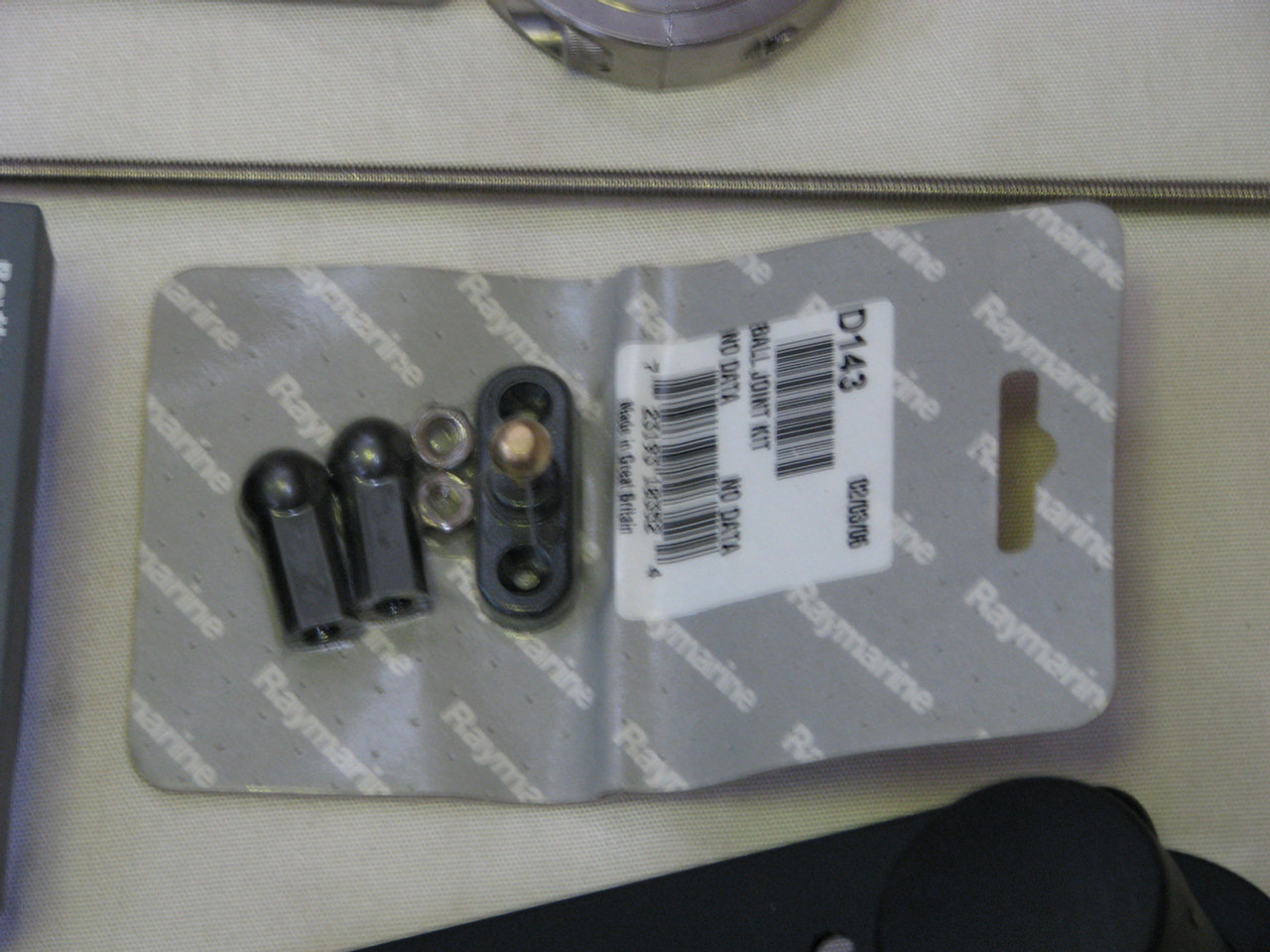
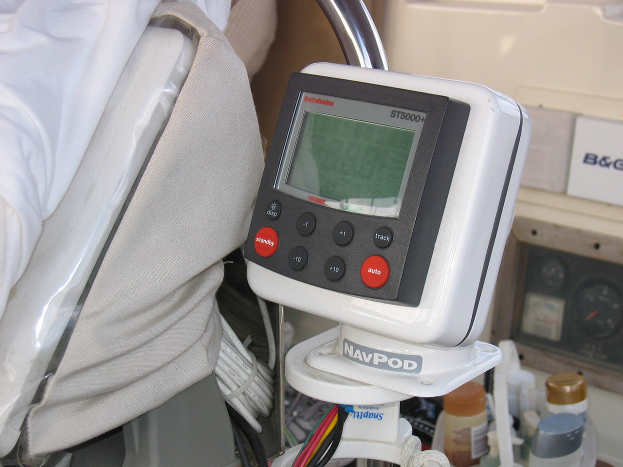
Raymarine 5000 CPT Mod (Never Implemented, as of 2014)
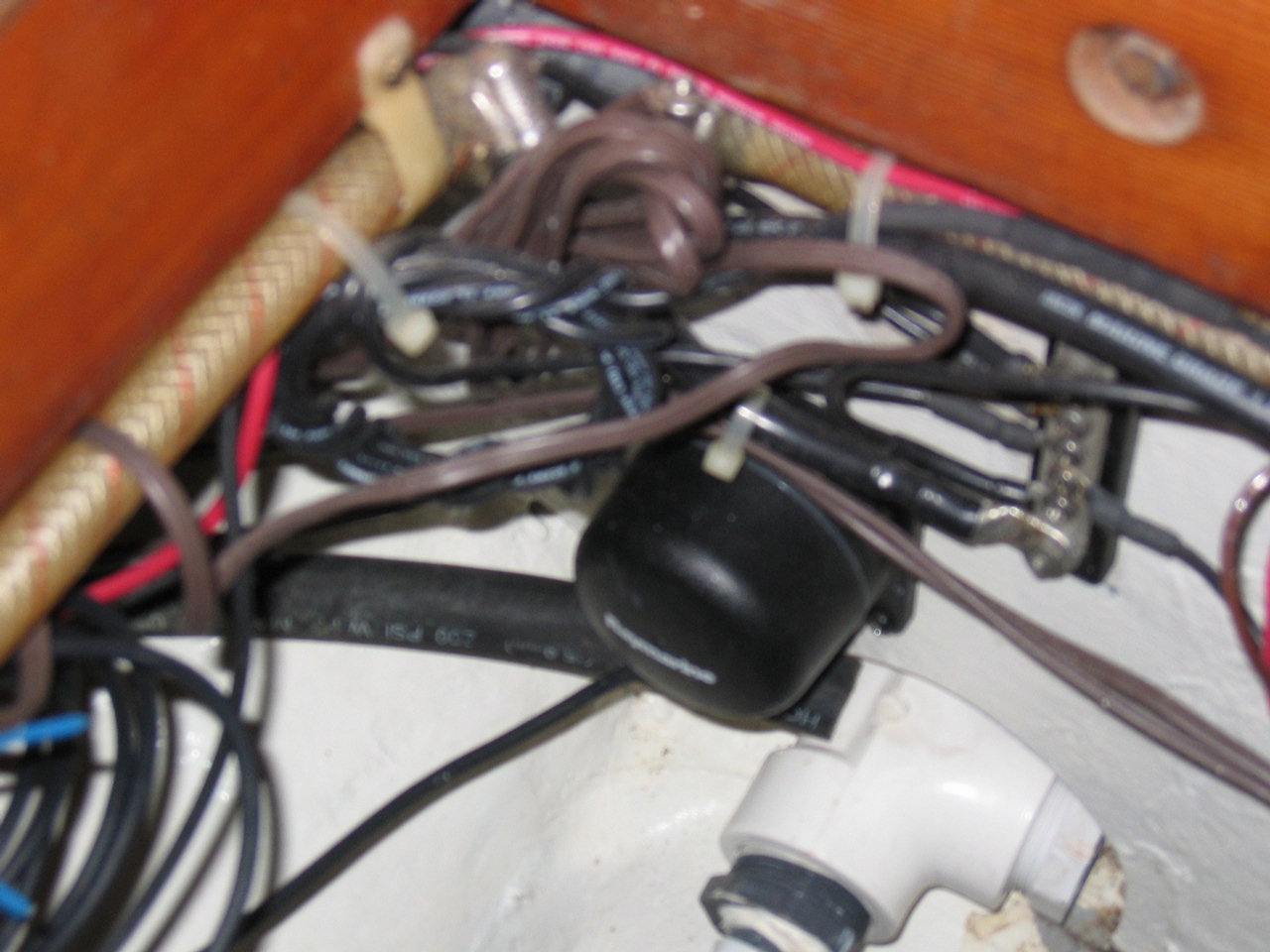
Below find pics of the components for a future project involving using parts from a Raymarine 5000 autopilot to substitute for the CPT brain and compass in order to allow the strong CPT motor to drive the boat through the smarter Raymarine control head unit and compass. According to our friend on s/v Peter Rabbit this works well and allows him to drive a route generated by his GPS and computer navigation system without having to continually adjust the autopilot. This would be very useful on a long passage with little wind. The Raymarine fluxgate compass and rudder angle indicator are also used with this system. Since this particular unit is no longer made by Raymarine it was available (in 2007) on Ebay for less than $500. There are also several pictures of the components Paul installed on his boat.
|
|
|

|
|
|
|
|
|

|
|
|
|
|
|
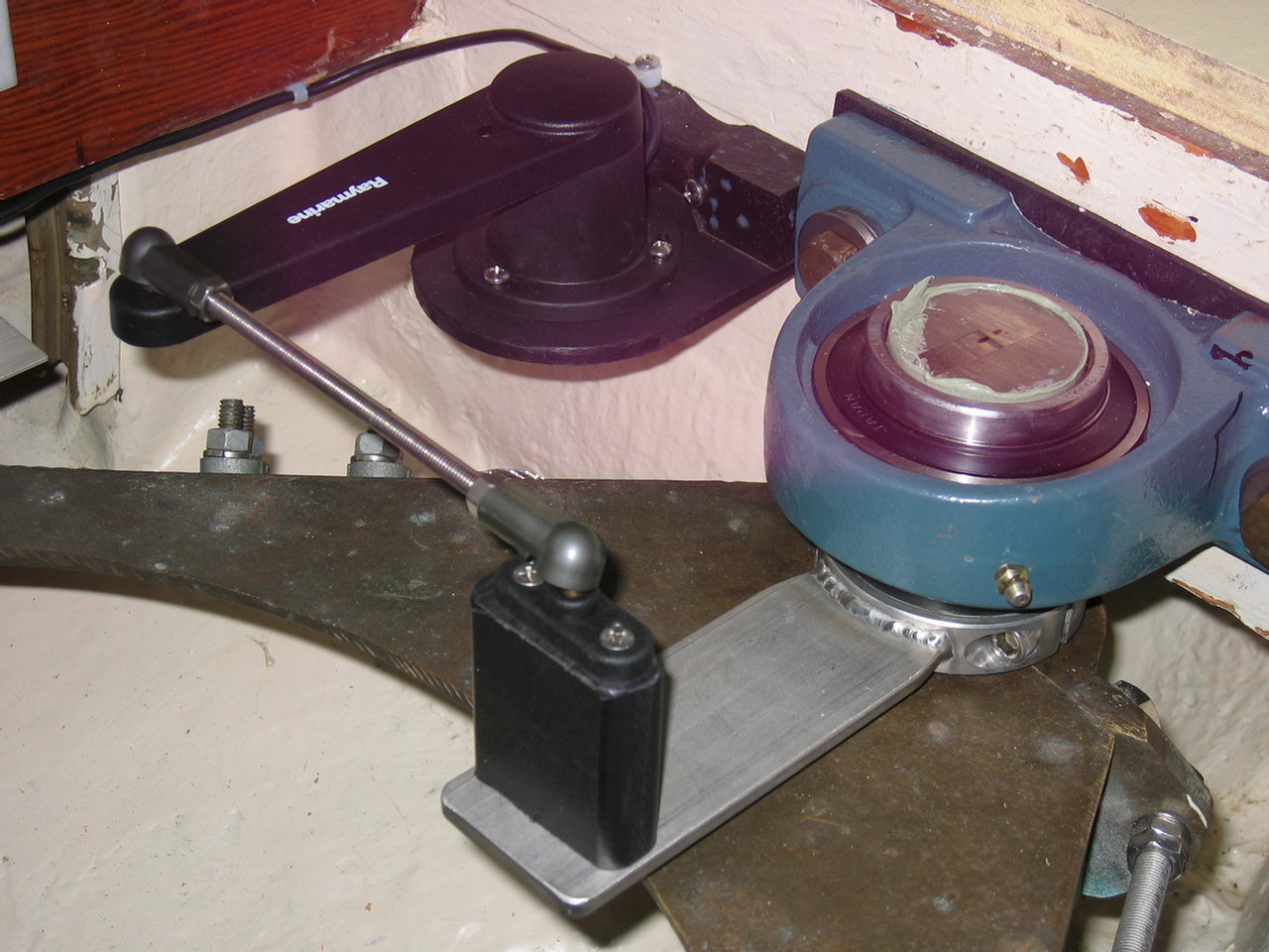
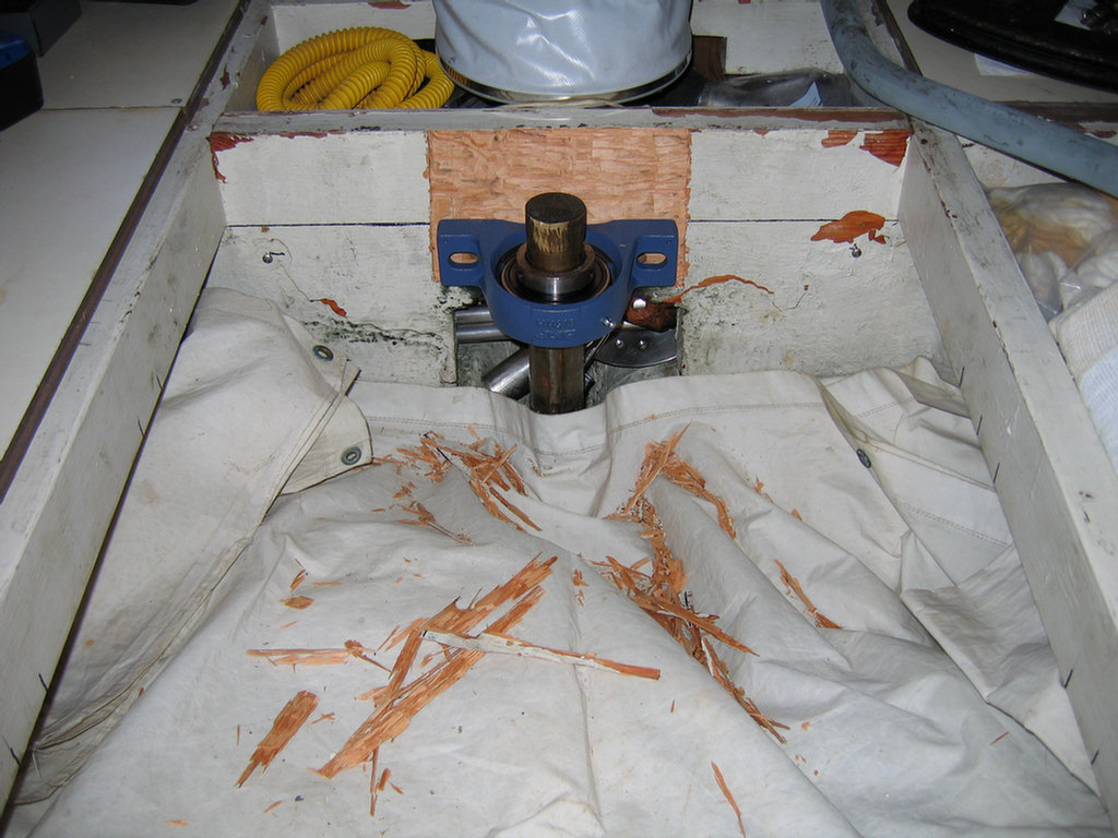
In order to take the weight off the delrin pad in the
underwater heel plate and allow the rudder to turn more freely this pillow
bearing was installed at the top of the rudder post under the aft berth.
By lifting the rudder assembly about a quarter inch and then installing the
pillow bearing on a strong bulkhead, the rudder now hangs on the bearing
instead of riding on the heel plate.
This gives a much smoother and stronger mount for the rudder.
|
|
|