|
CSY |
|


|
Home Page |
||
|
CSY Workshop Home |
||
|
Soggy Paws CSY Home |
||
|
New Cat Workshop Pages |
||
|
Engine |
||
|
Electrical Systems |
||
|
Plumbing
Systems |
||
|
Refrigeration |
||
|
Rig
& Sails |
||
|
Hull |
||
|
Cockpit |
||
|
Deck |
||
|
Interior |
||
|
Steering |
||
|
Electronics |
||
|
Computers |
||
|
Workshop Links |
||
|
Miscellaneous |
||
|
About Us |
||
|
Contact Us |
||
|
About CSY Boats |
||
|
See more 'boat project' discussions by Dave on the CSY Owners Forum |
Last Updated: 5/1/2017
Future Additions:
Engine Belting
Air Cleaner
Oil Hoses
Alternator Overhaul
Transmission Removal
Engine Removal
Engine-Transmission Spares
Perkins Engine Numbers
I looked up your engine number and you have a 4154 (GA), built in USA (N)
and 1980 model (G). The first set of numbers are used to ID parts and the
second set is the serial number of the engine. If you look at your engine
and the air filter and intake manifold are on the port side, you have the
old style NA engine. It looks like your engine is the same as mine. This
info is in the engine Operating Manual.
Paul Barbour sent me the Perkins Engine Codes guide he got off the internet.
I've cleaned it up a little and posted it on our website here:
http://svsoggypaws.com/files/perkins_engine_codes.pdf
This came from ARSCO, which has Perkins and other brand parts and
also a engine part number references to other models.
See my Workshop Links page for a link to ARSCO's website.
Engine Overhaul Tips
Parts quote can be obtained here or any other Perkins distributor:
Parts Supply Corporation
4700 118th Ave
Fennville Michigan 49408 USA
Phone 269 673 4146
Fax 269 673 7226
email: sales1@parts-supply.com or parts-supply@btc-bci.com
Website: www.parts-supply.com
See my Workshop Links page for links to suppliers referenced below.
More Parts info for Perkins 4-154 (older
version, not 200 series):
Engine Overhaul Kit $1674.00
Includes: pistons, cylinder liners/sleeves, piston rings, piston pins,
piston pin retainers, big end connecting rod bearings, main crankshaft
bearings,
camshaft bearings, piston pin/small end rod bearings, complete engine gasket
and seal kit, front crankshaft seal, rear crankshaft seal
(7 Nov 2009 CSYO Post) I haven't priced any of this recently except
the rear main seal. It just jumped from about $30 to $41 for both halves.
Ten years ago it was about $8 per half. I spent about $3000 on my complete
overhaul in 1998. I did all the disassembly, reassembly and preservation. I
needed a new camshaft, the cylinders sleeved, a valve job, a $300 basic
transmission overhaul, a new timing gear cover plate, and some other minor
items not mentioned below in your quote.
Here are a few other things to consider and some 'while I'm at it' projects
that I remember from my overhaul:
-
Use an electric impact wrench (Harbor Freight) to disassemble the engine-that will make it a lot easier. You will need a good torque wrench and sockets to reassemble
-
Keep all your fasteners and small parts in clear plastic bags labeled with what system/part they came from. I replaced many fasteners with stainless
-
For your cylinder head work use only a very reputable machine shop experienced in cylinder head repair. Be sure you get the cylinder head checked to make sure it is not warped on the bottom and not leaking from an invisible crack. Mine was warped and it leaked when reinstalled. Make sure the shop grinds AND laps the valves to the seats, mics and checks the valve stems for wear and uses new valve seals.
-
Have a good radiator shop acid clean and leak test the salt water cooling tube nest and the oil cooler.
-
Make sure you have all the gaskets. I think the kit does not include some of the ancillary equipment gaskets like the thermostat. I'm not sure that was one of those missing but there were a couple not included. There are also some extras.
-
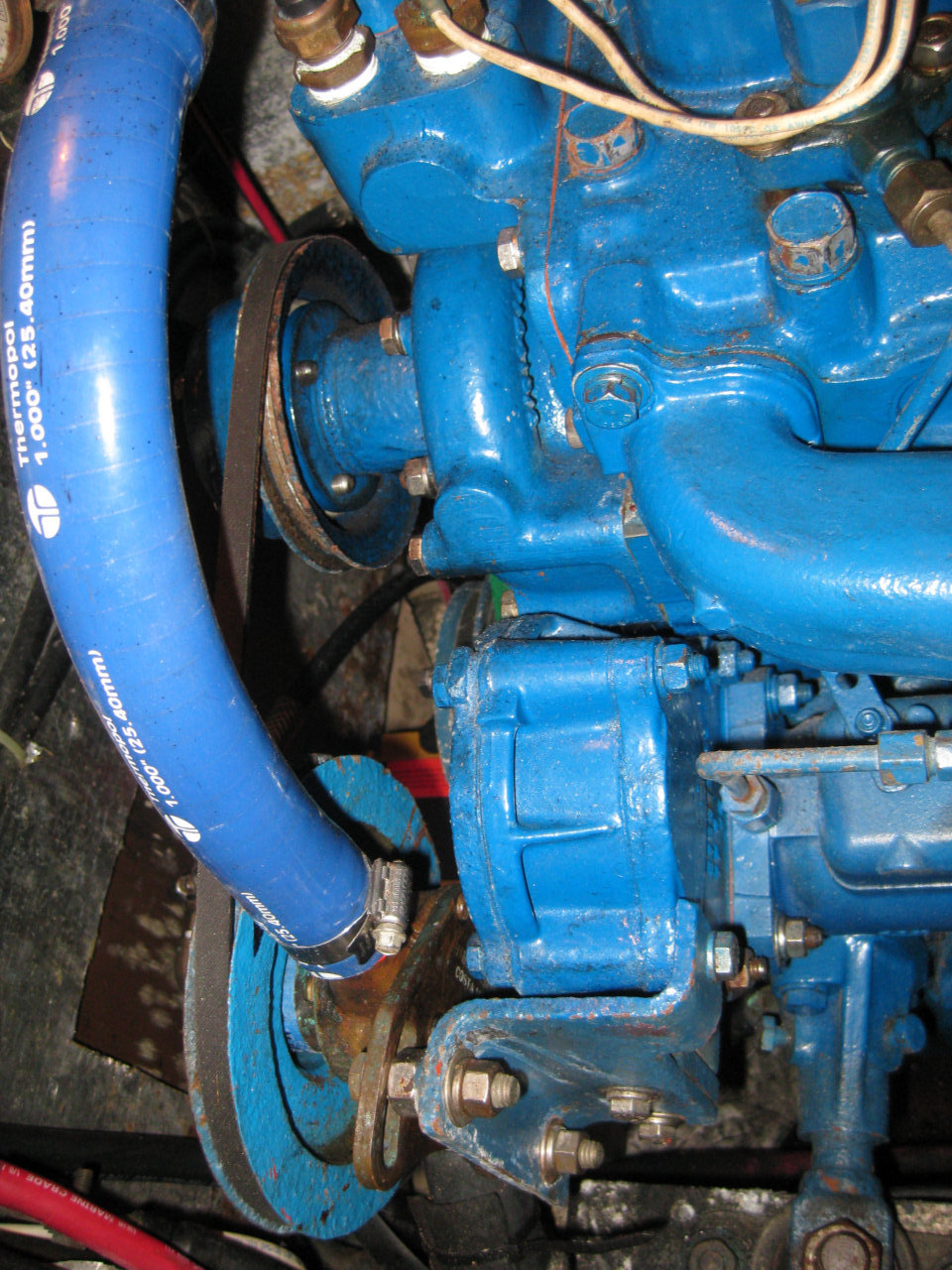
Use the new Thermopol blue silicone engine cooling water hoses. They are more expensive but the runs are not long and they last forever.
-
Take the block, cylinder head, transmission and everything else you can down to bare metal and repaint. A needle gun will be a big help in this effort. I used phosphoric acid, spray metsl primer and then spray Old Ford Blue to paint my engine. OFB is the same as original Perkins blue. Use Hi Temp spray for the block, cylinder head and exhaust manifold.
-
Have someone check the oil pump for wear. The specs are in the overhaul manual.
-
Check to make sure you have the gasket for the rear main seal housing-it is not mentioned in the overhaul manual during installation.
-
Look at reversing your crankshaft pulley so you can get two belts on the alternator (if over 100 amps) and one belt for both water pumps. This keeps you from having to fix or replace the alternator if you have a problem in a tight situation. Just remove or cut the alternator belts. The pumps still work on their own dedicated belt and you don't need the alternator to run the engine. You will have to do a bit of shimming to get the pump lineups right. Depco Pump in Clearwater is the best source for all pump parts.
-
Use Whitehead LP fittings and LP oil hose, not hydraulic swaged fittings/hose for all your oil lines. You will never see oil pressure over 60 PSI, and with this system you can carry spare hose and replace lines whenever you want on the boat.
-
Look carefully at your motor mounts and their lag bolt mounting arrangement. It is better to get the lags into a sheer situation on the side of the motor skids with aluminum brackets.
-
Move your oil pressure sensor from down low on the port side of the engine up to the aluminum block with multiple outlets near the oil filter. Mount a threaded nipple on the engine and run an oil hose to the aluminum block.
-
Look at the several new extended oil change systems using synthetic oil and better filtration now available. I am using the one from Amsoil.
-
Install double fuel filters with a vacuum gauge. You can make this up yourself as I did from two filters and some Home Depot brass fittings and valves.
-
Add an electric fuel pump in series with your lift pump for back up and bleeding the engine.
-
Make a custom drain pan to catch drips under the engine. I made mine out of thin copper plate and just bent the edges up to form the sides.
-
Add a low point oil drain hose that you can access to change oil. I drilled and tapped the big plug at the aft port end of the oil pan for a nipple to attach the hose.
-
Add low point drain hose fittings for the engine fresh water coolant to the bottom of the oil cooler and salt water heat exchanger so you can drain most of the coolant out of the engine during a change. There is still some left in the block but not too much.
-
Take all your small electrical wires to a long terminal block mounted at the aft end of the engine above the oil filter.
-
Install a modern cleanable air filter. You will need to make an adaptor. KD is a good brand.
-
Install a spin on secondary fuel filter adaptor. This makes the fuel filter changes much less messy. Complete Yachts sells them.
-
Remove and carefully inspect your packing box and stern tube hose. Change the packing and maybe get a new 5 ply hose from Buck Algonquin through Lewis Marine in Ft. Lauderdale.
-
Take a close look at your exhaust system-raw water injection elbow, siphon release, exhaust riser, water muffler, and exhaust hose. I use a T and a ¼" hose to my cockpit drain for a siphon release at the top of my raw water cooling hose just before it goes down to the injection elbow.
-
And finally, while the engine is out, take the time to thoroughly clean and repaint the engine bilge area so everything will look bright and shiny when the engine goes back in.
See my overhaul notes here.
Raw Water Pump
(25 Jan 2010 CSYO Post) The standard old style Perkins 4154 engine had
the Jabsco raw water pump mounted on a bracket on the port forward corner of
the engine, above and in front of the fuel injection pump. It had its own
belt to the crankshaft pulley. The small stock alternator and fresh water
pump were together on a separate belt. And the refrig compressor was belted
the third/outermost/forward crankshaft pulley.
In the pic you sent, it looks like a flange has been substituted for the raw
water pump pulley and it is bolted to the front of the non original aluminum
crankshaft pulley. I believe the flange turns the pump shaft and impeller
while the hoses hold the case stationary. It looks like the impeller would
be accessible from under the plate on the front of the pump with only the
hoses in the way. This is a most unusual arrangement and certainly not
stock.
If you decide to make changes I would recommend considering
belting the two pumps together and the alternator separately. If over 100
amps, use two belts on the alternator, as big alternators can use up to
about 5 HP, and a slipping belt will severely overheat the alternator. With
this arrangement if you have an alternator bearing failure, you can still
run the engine by cutting or removing the alternator belts until you get it
fixed or replaced. Both pumps are necessary to run the engine at speed and
they require little HP so they might as well be belted together.
Incidentally, those Jabsco/Sherwood bronze raw water pumps are not cheap at
about $300. I now have 4 aboard, all found at flea markets for less than $50
ea. They are not hard to rebuild but the parts are expensive.
Take a look at my Perkins 4154 Engine Pics here.
For a new pump or parts try Depco Pump in Clearwater, FL.
They have everything you will need. The original was a Jabsco 11850.
Propeller Choices
There are quite a few feathering/folding
props to choose from. I even saw a 4 bladed one on a Bavaria recently, but
couldn't find the make. There's no question that a feathering prop is the best
choice for pure sailing. I believe almost 3/4 knot faster. The down side is
the huge difference in cost. New cost $3-4K vs about $.5K. I bought a used
fixed prop as a spare a couple of years ago for $50, and then had it
balanced and the blade pitch adjusted, so they are still available.
For a feathering prop you might also ask what happens if you hit something.
Can you replace it with a spare in the water or do you have to haul the
boat? And can the prop be fixed at a standard prop shop or does it need
factory service.
During the 12 years we have used the original fixed blade prop on our 44 WT,
we have have not had the noise problems mentioned by some. We hear no prop
rotation noise unless sleeping in the aft stateroom, and then I've never not
been able to sleep because of the noise. I would think that shaft (if
original) scoring would more likely be caused by the twenty some years that
the 304 SS shaft was in the boat not any additional shaft rotation. Too
tight a stuffing box or something in the cutlass bearing might be a more
likely cause of shaft scoring. When I changed my original shaft out a couple
of years ago it was pitted at the stuffing box, but not scored. The new
shaft I purchased was made of the best modern shaft material, Aquamet, which
uses a blend of better underwater metals more resistant to salt water
corrosion. It comes in several grades.
For those that want to lock their shaft, there are several methods
available. One is an expensive, commercially sold shaft lock that is very
good. Also, a light line fastened to something solid with a loop over a
coupling bolt head will hold the shaft from turning. Sherry's dad used the
line method for many years. To get motoring again from a locked shaft you
simply reverse for a couple of seconds to throw the line off and then go
forward. If you forget to reverse first, the line breaks when you go
forward. We have used this method to lock our shaft for over 4000 miles and
it works great.
It would be interesting to know just how much a feathering prop will
increase a CSY's boat speed. Most of the literature and others I have
talked to say 1/2 to 3/4 knot. Of course near hull speed there is no gain.
If the gain in speed for a CSY is nearer a knot then that is 20% gain at
five/six knots or several days over a long passage.
I believe that Maxprops are feathering, not folding, so if a blade gets hit
it would not move/fold except to turn on its axis. In that case, the issue
would be whether a gear tooth or some other internal part would break. And
if something did break where it could be repaired. Certainly not at some
third world prop shop, which could repair a fixed prop.
A major selling point in my mind would be, could I replace a damaged
feathering prop with a spare fixed prop in the water. If not, that's a big
problem. Anyone know which can and which cannot be replaced underwater?
Finally, I know that Practical Sailor and maybe other periodicals have done
propeller evaluation articles. Those would certainly be worth looking at
before purchase.
Exhaust Thruhull Cover
(18 July CSYO Post) Originally all the
exhaust thru hulls were placed a few inches above the design static water
line in the transom. Now that we are fully loaded, with lots of 'stuff', I
have raised the painted water line so that my exhaust thru hull splits it.
It is underwater when underway. This only adds a minor amount of back
pressure to the exhaust system and is not a problem.
For about every 1500 lbs you load into the boat you raise the waterline by
1". So you must have more than the average amount of beer onboard.
You can help the splatter and prevent sea water from being forced up the
exhaust hose while sailing in a heavy following sea by installing a cover
over the exhaust. I used a piece of 1/4" rubber matt bolted to a piece of
starboard. Then I screwed the starboard into the transom around the thru
hull. I made mine custom because I couldn't find a commercial unit to fit.
It has been on a year now and works well.
Engine Raw Water Siphon Release
(25 Jan 10 CSYO Post) Last week we talked with a new cruiser anchored in
Costa Rica that had just flooded his engine with 1.5 gallons of salt water,
probably because of the lack of a siphon release and a high loop in the raw
water cooling line on his engine. The siphon release in the raw water line
is a seldom looked at but very important item. He eventually flushed his
engine twice with new oil and finally got the engine going a day later.
After reading several articles about this issue, now 12 years ago, I
installed a 1/4" hose from the top of the raw water high loop to the plastic
thruhull in my cockpit drain. Now whenever the engine is running I have
visual proof that the raw water system is operating and when I shut the
engine down it acts as a very reliable siphon release. Since that time I've
seen many boats with that or similar systems. Oyster runs their hose in
copper overboard through the side of the boat.
Commercial siphon releases with a spring and one way valve can get clogged
with salt and cease operating. If that happens you have a real problem. And
you have no visual reference that the cooling water is flowing.
So when you run out of things to do on your boat there's another, but very
important, project for you.
I have no pics in the Workshop section of our website, and I don't think
that I've taken any. It will have to wait until we get back to the boat in
Nov. I'll post pics of our setup then.
The lashup is as simple as it sounds, just use any convenient fitting at the
top of your high loop in the raw water line that you can get a 1/4" ID hose
on to. Run the hose to a 1/4" fitting tapped into the plastic thruhull
fitting that forms the cockpit drain. The tap in the cockpit drain should be
a couple of inches down so that it doesn't splatter saltwater into the
cockpit but you can still see the water stream coming out when the engine is
running. The fitting on the cockpit drain should be higher than the top of
the high loop. This is all low pressure warm salt water so nothing special
required except water tight connections.
There are other ways to do this, but this setup has worked well for me for
many years.
Basic CSY 44 Engine/Transmission Info
(25 Jan 2010 Post) I keep an overhaul manual,
owners' manual and parts list aboard for my Perkins.
I've looked at a lot of 44s in the past 20 years and the engines seem to be
a mix of Westerbeke and Perkins, mostly the 60 HP models. I suspect the 85
HP Perkins was an upgrade, maybe from the factory, maybe from a subsequent
owner. I believe all boats with Yanmars, Catapillars, Volvos, etc were non
factory upgrades.
There is information on this subject in the CSY Guide to Buying a Yacht,
produced by the factory, which many owners have a copy of.
I have the original Perkins 4154, completely overhauled in 1998, in my
Walkthru #35. I find it to be entirely adequate for the boat, and am not
tempted to change, especially at $15 K for a new engine install. After
collecting for years, I now have a good stash of rebuild and spare parts
aboard. Most parts are still available, from dealers and elsewhere, both new
and used with a bit of scratching around, as there are thousands of these
engines still in use around the world. (However, recently Perkins factory
announced they are no longer producing 4154 parts). The same is true I
suspect for your engine. So, if you are keeping your engine, keep your eyes
open for owners selling off high value used parts for your Westerbeke (like
the cylinder head, injection pump, heat exchanger, starter, etc) as they
upgrade to new engines. And buy a complete gasket kit and spares like
thermostats, injectors, fuel lines, pumps, etc. Then you will have these
items readily available should you need them in the future. I see it as
cheap insurance against having to spend thousands on a short notice
replacement, shipped in by banana boat to some out of the way place.
I also have a factory rebuilt Borg Warner Transmission. Rebuilt units with new
parts are readily available at good rebuild shops and used units are
available at the used marine equipment stores. Be careful if you have to buy
a rebuilt transmission. There is a big difference between a rebuilt
transmission done with a mix of original ("look OK") and a few new parts and
one done to factory specifications with all parts "new or as new". A factory
rebuilt BW Velvet Drive will run you about $2,000.
According to the designer, the hull speed on a CSY 44 is about 8.4 knots
(Fineness ratio, 1.4, times the square root of the waterline length, 36'=6).
For a displacement hull, like the 44, there are only 4 ways to exceed that:
1 Surfing down a really big wave
2 With substantial current pushing you along
3 Having something in the order of a 1000 HP engine in the boat driving a
10' diameter prop
4 Having had one too many beers before looking at the GPS/knotlog
1980 Perkins 4154 Engine Overhaul
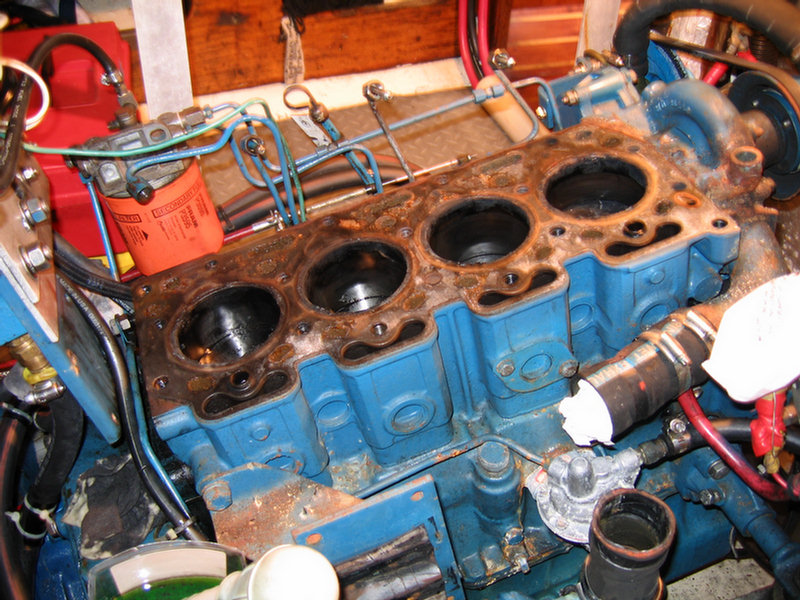
(Topica Post 2004) I have a Perkins 4154, vintage 1980, old style. With my Perkins Workshop Manual in hand I completely overhauled it in my garage in 1998--a long, somewhat expensive but very educational and worthwhile project. Now, 6 years later, I'm convinced that my $3000 overhaul done by me was a far better decision than a $10,000 replacement done by someone else.
Now I know what makes Mr Perkins tick and how to diagnose and repair it without having to hire help at $50+ an hour or worse be towed in from some remote location at $150+ an hour. I treated the overhaul kind of like a 6 month college course in diesel mechanics. The hardest part was keeping track of all the fasteners and their replacements. I still ended up with a hand full of extras which I saved just in case. This overhaul also gave me access and time to consider improvements I could make on the engine and in the engine room.
Amongst the changes I made were things like:
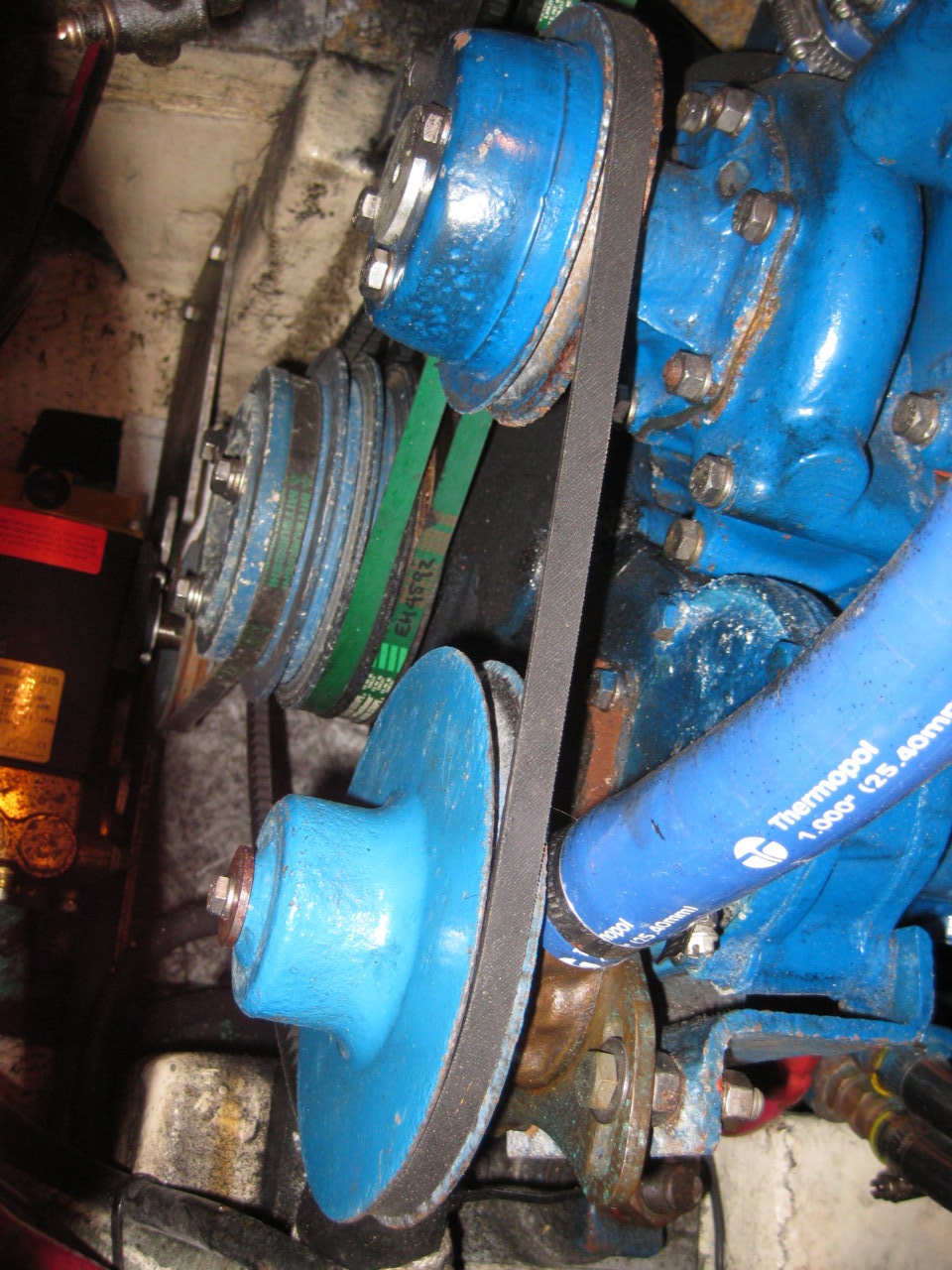
- rearranging the pulleys so that
the two water pumps were belted together and the new high output alternator
got two belts instead of one
- plumbing an oil drain hose up from the
bottom plug in the sump
- adding dual Racor filters plumbed in parallel to facilitate a quick
underway filter change
- adding an adapter to the secondary engine fuel filter mount to allow using
a common spin on filter
- adding an Amsoil bypass filter system and changing to Amsoil synthetic oil
in order to increase the oil change periodicity-see detailed info below
- moving all the engine wire harness wires to a common terminal board
mounted aft on top of the engine to improve access
- mounting two oil sensors and an oil sampling tap on the aluminum block
manifold aft on top of the engine
- changing to a cleanable KD air intake filter with adapter and housing
- adding a Drive Saver between the shaft coupling halves
- adding a copper drip pan under the engine
- adding an all 316L SS exhaust riser leading to a new fiberglass lift
muffler mounted in the far aft starboard corner of the engine room
- plumbing a raw water flow indicator tube from the siphon release U in the
exhaust raw water line to the port cockpit drain
There are also many other things you can do to this engine to improve serviceability and access while it is out of the boat. Although my engine had only 6000 hours on it, it had major problems even though it ran well at the time. Had I not overhauled it before we left on our Caribbean cruise it would have soon been a disaster. (top)
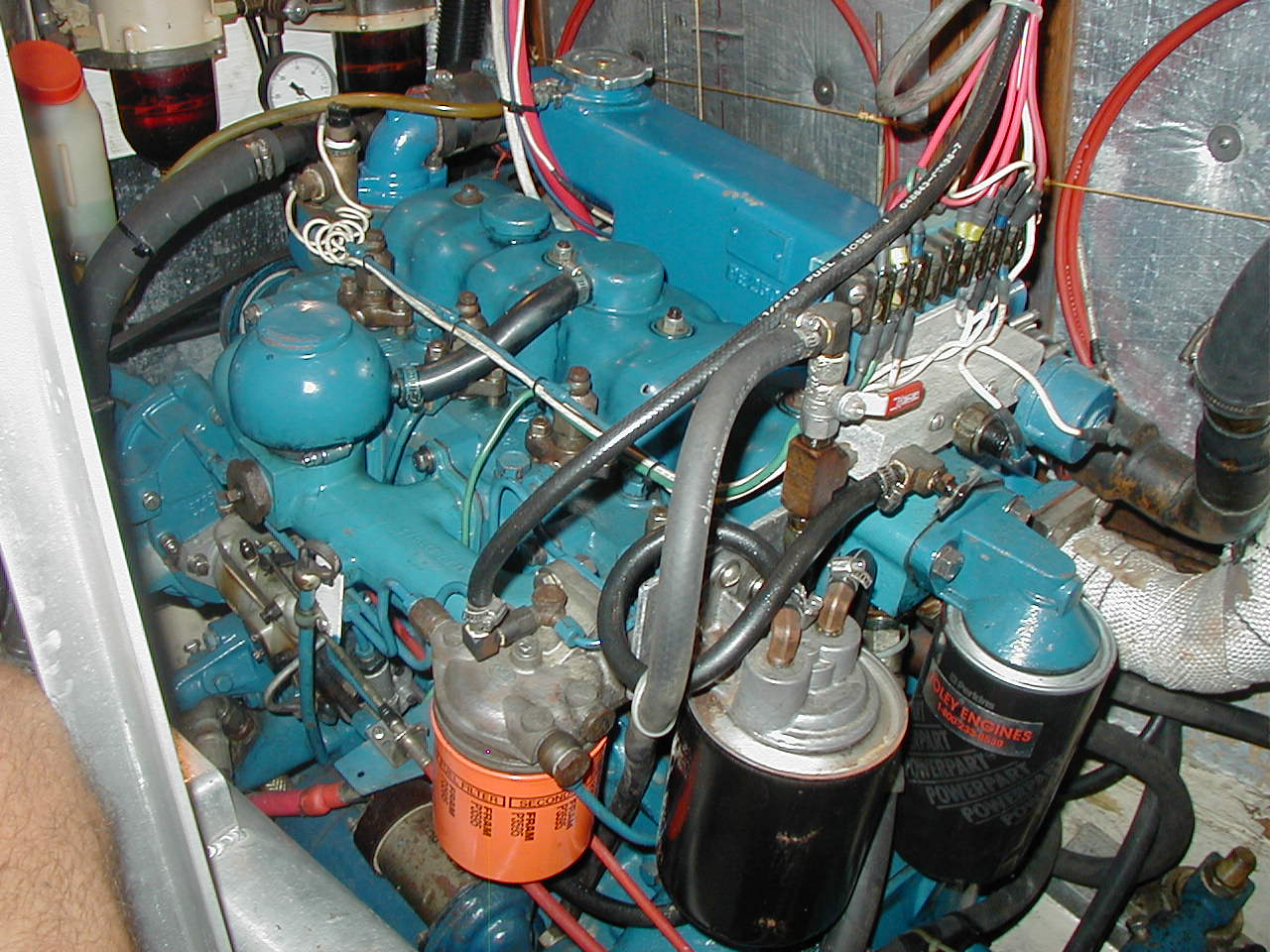 Aft end of the engine showing the orange spin on fuel filter and adapter, easy access electrical connector block, Amsoil Bypass filter system and the oil sensor mounting block with sensors and a tap for taking oil samples. |
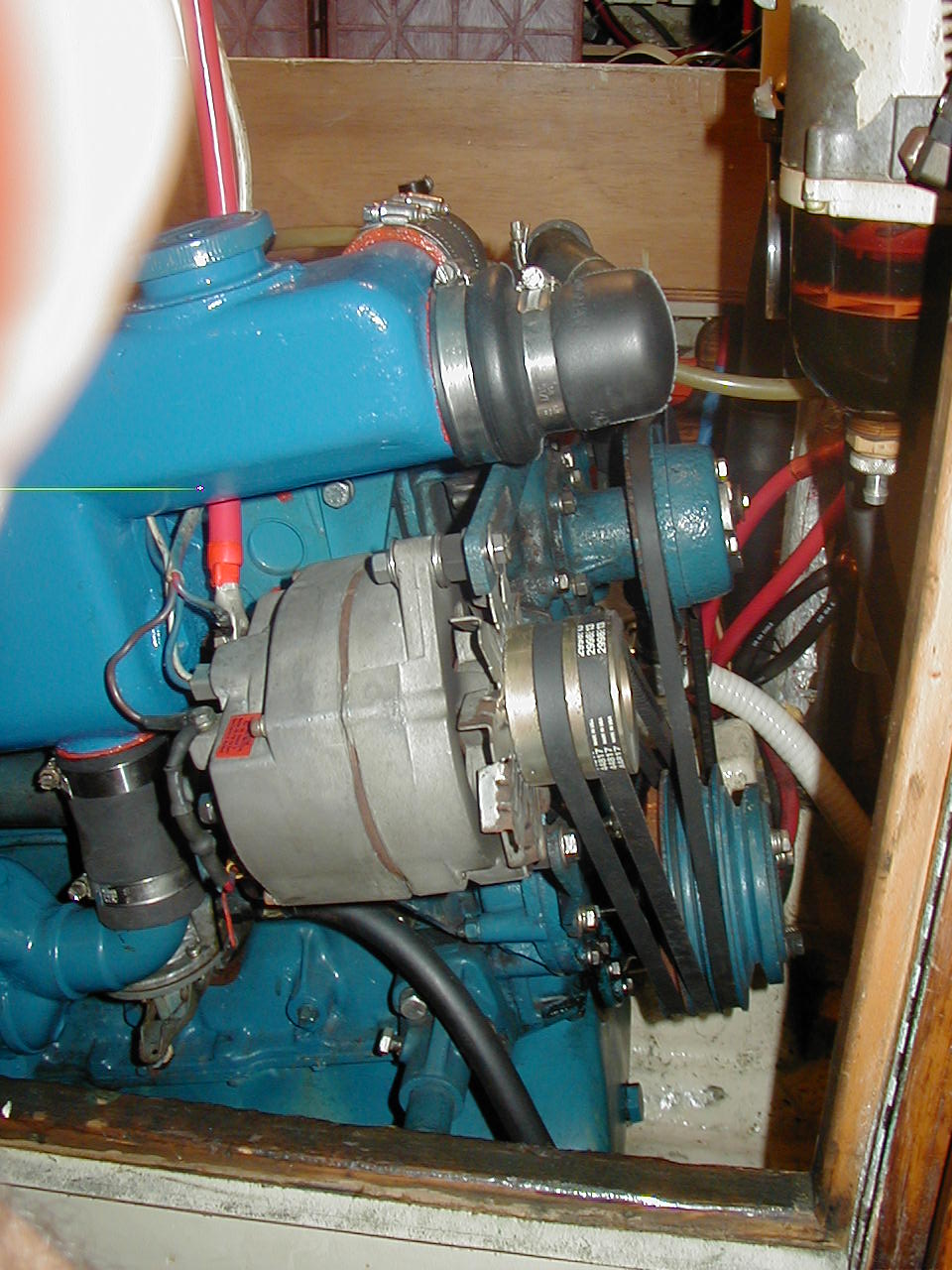 Front starboard side of the engine showing the dual alternator belts and the single belt driving both the fresh and salt water pumps. |
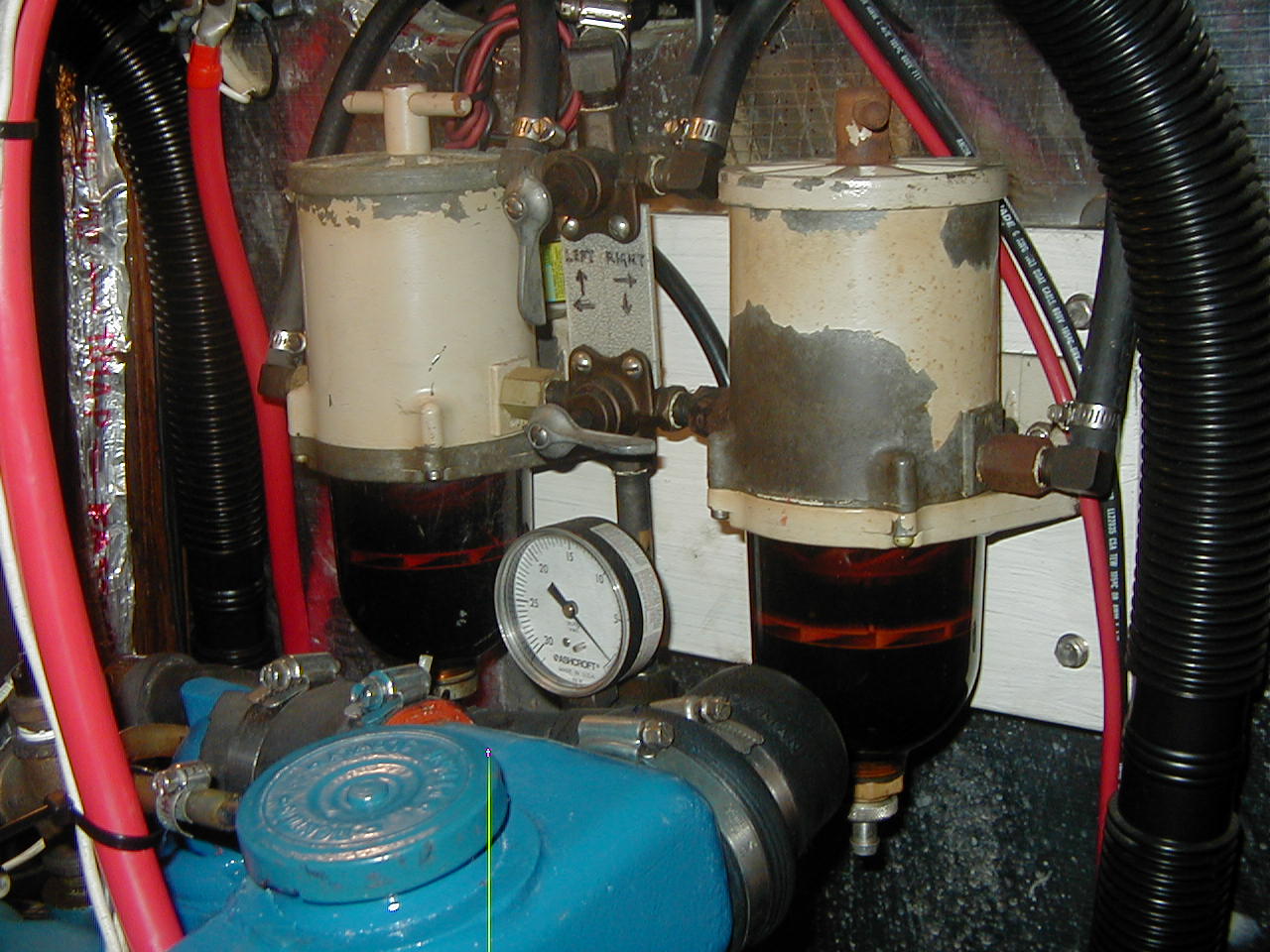 Front engine room bulkhead showing the dual Racor 500 fuel filters set up for quick changing on the fly and the vacuum gauge for monitoring filter condition. |
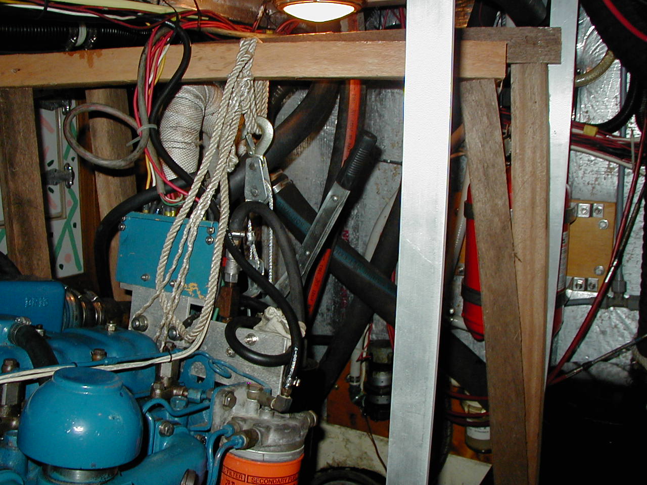 Wooden supports for the ratcheting chain hoist used to get the transmission in and out. Once free of the engine the transmission is guided to port and set on the aluminum floor so that it can be lifted out of the engine room hatch by the main halyard. |
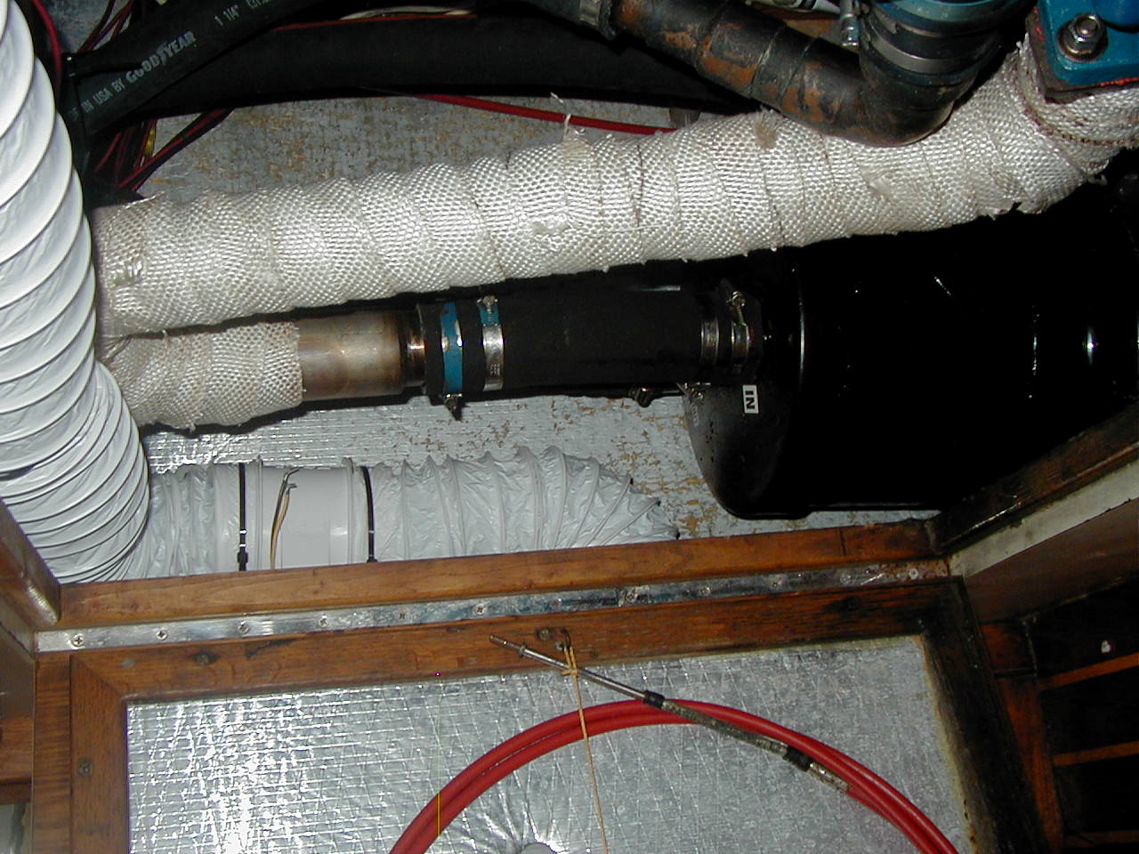 Aft starboard end of the Engine Room showing the new SS exhaust riser and water lift muffler. |
 New aft aluminum motor mount brackets with two 1/2" SS lag bolts set in sheer to help prevent the engine from moving in a knock down. |
 Forward starboard side of the Engine showing the ventilation ducting to provide fresh cool air from the Galley to the alternator. |
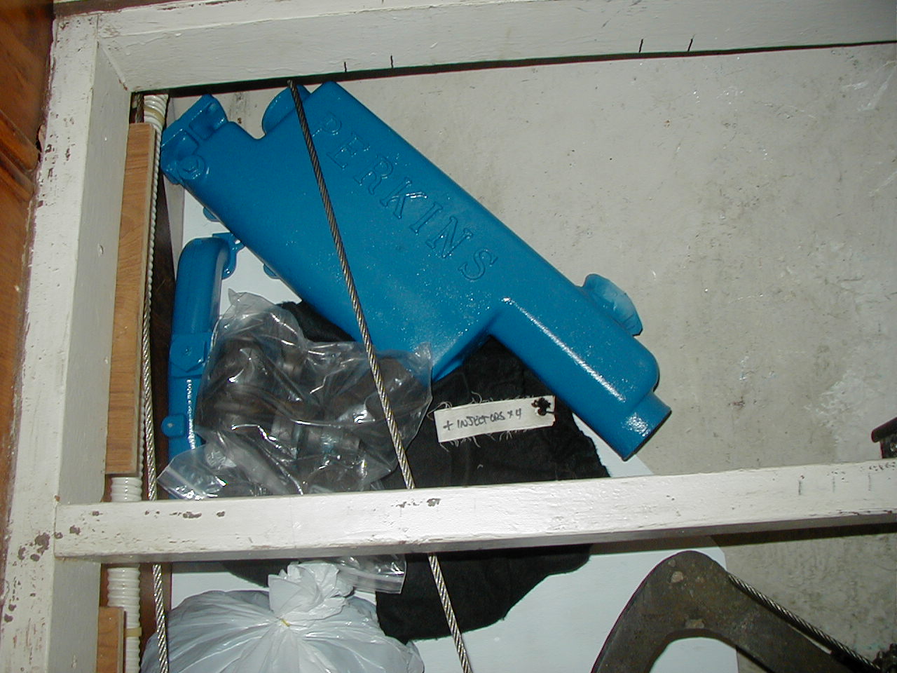 A few of many engine spare parts stowed under the aft berth. |
Perkins Engine Numbers (reference PDF file to interpreting your engine serial number)
Troubleshooting Fuel Pump Leaks
First make sure the black knob on your binnacle that you pull up to stop the engine is the fuel cut off for the injection pump. I have the same. It is not a compression release. It must be down in order to start the engine as no fuel will get through the injection pump if it is up. If the engine turns over but won't start look at that first. Also, it is worth carrying a spare cable for this and the throttle. They are commonly available Morse cables. You need to know the length and what end fittings you have.
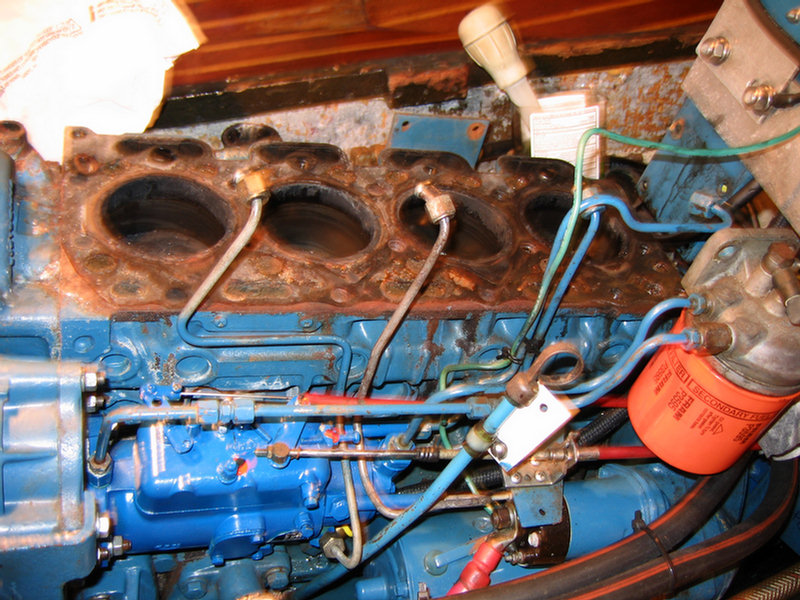
(Topica Post 2004) There are at least two fuel pumps on the Perkins 4154 engine-- the mechanical lift pump on the starboard side and the injection pump on the port side. The lift pump is about the size of a doughnut and deals with pumping fuel at low pressure. The injection pump takes the low pressure fuel and feeds it to the injectors at a much higher pressure. Depending on where you are working in the fuel system there is rubber hose and 1/4" metal fuel line (the same size as 1/4" brake lines). The rubber hose should stop at the lift pump. The rest of the lines running through the secondary fuel filter, the injection pump and to the injectors should be metal. There is also a metal return line running along the top of the injectors back to the filter. From there back to the tank will be rubber hose.
The devices used to seal these lines to their various attachments include hose clamps, aluminum/soft copper washers, rubber olives and expanded ends. By looking carefully with a strong light you should be able to identify where the leaks are coming from. In most cases a slight tightening of the joint will seal the leak. About the only place you have to be careful not to over tighten is the joint at the injectors ("high pressure fuel pipe nuts") where you could crack the expanded end of the high pressure injector line (each one is $35 so be careful). The spec is 15 foot pounds or "tight but not real tight". If tightening down a bit doesn't solve the problem, loosen up the joint, take it apart and have real good look with a magnifying glass at all the parts until you find the problem. It doesn't take much in a high pressure line to cause a small leak.
A good injector
repair shop should have the olives and maybe the washers. Aluminum/soft
copper washers are also available at a good local hardware store. I use Tradewinds Diesel in Miami (commercial discount available) or Complete Yacht
in Ft Lauderdale (new and used Perkins parts) when I need Perkins parts.
However, there are many other good Perkins dealers around the country.
If the leak is on the body of the lift pump you can no longer buy parts,
except outside the US, so go to a Perkins dealer for a replacement for about
$50. You could also replace it with an electric pump as long as the pressure
is right and you are willing to trust another electric motor. Or maybe the
best situation, plumb both mechanical and electric pumps for use one at a
time with the other as backup.
If the leak is on the body of the injection
pump you should take it to the best injector shop you can find with a clean
room and experience in your pump. Injection pumps should be overhauled every
2500 hours according to the repair manual and Everglades Diesel in Ft
Lauderdale where I take mine. There is good reason for that periodicity due
to the risk of major problems and expense if the injection pump seals fail
in the wrong place. You should never attempt to take the injection pump
apart yourself because it requires specialized tools and a very clean
environment. That is why there is no info on overhauling it in the workshop
manual. Just in case I acquired a spare a few years back and have
it stored away ready to install if needed. (top)
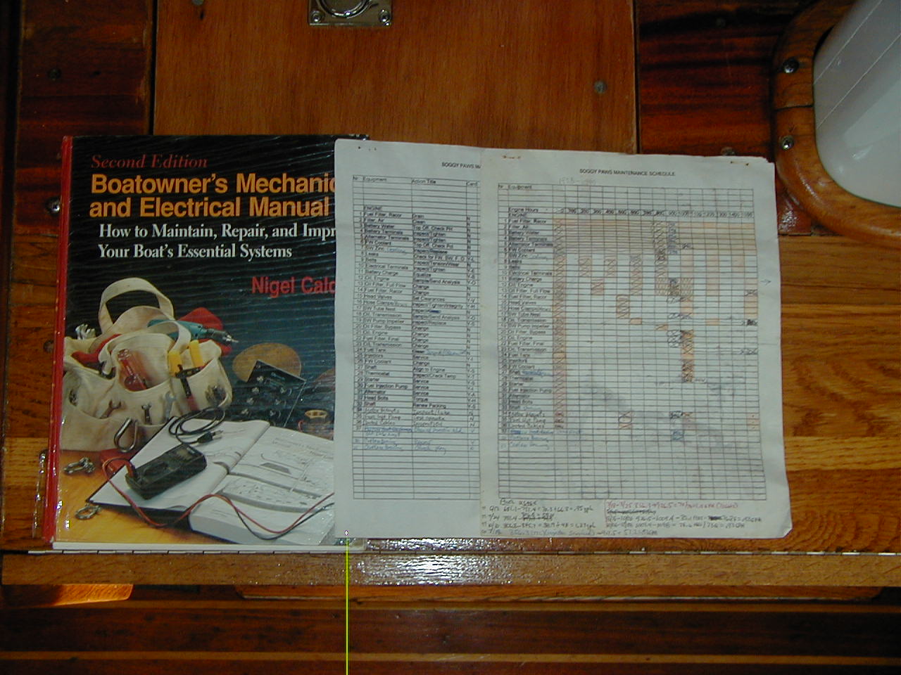
Recommended Reading: Diesel Repair Manuals
(Topica Post 2004)
Regarding good diesel manuals and obtaining advice I would recommend
obtaining a copy of one of Nigel Calder's books:
Marine Diesel Engines or
Boat Owner's Mechanical and Electrical Manual.
Both are available on Amazon.com as paper books or ebooks.
You should also have onboard the two Perkins manuals--4154 Workshop Manual and Operators Manual for Marine Diesel Engines and maybe a parts manual. It's well worth doing your homework by reading these manuals and learning your engine before something goes wrong and you end up spending a great deal of money for someone else to fix it. Armed with the knowledge from these sources you will also be better able to seek and evaluate any advice you may obtain--including the above. (top)
 |
 |
Engine Room Pictures
 Aft stbd corner, vent system, lift muffler and exhaust riser |
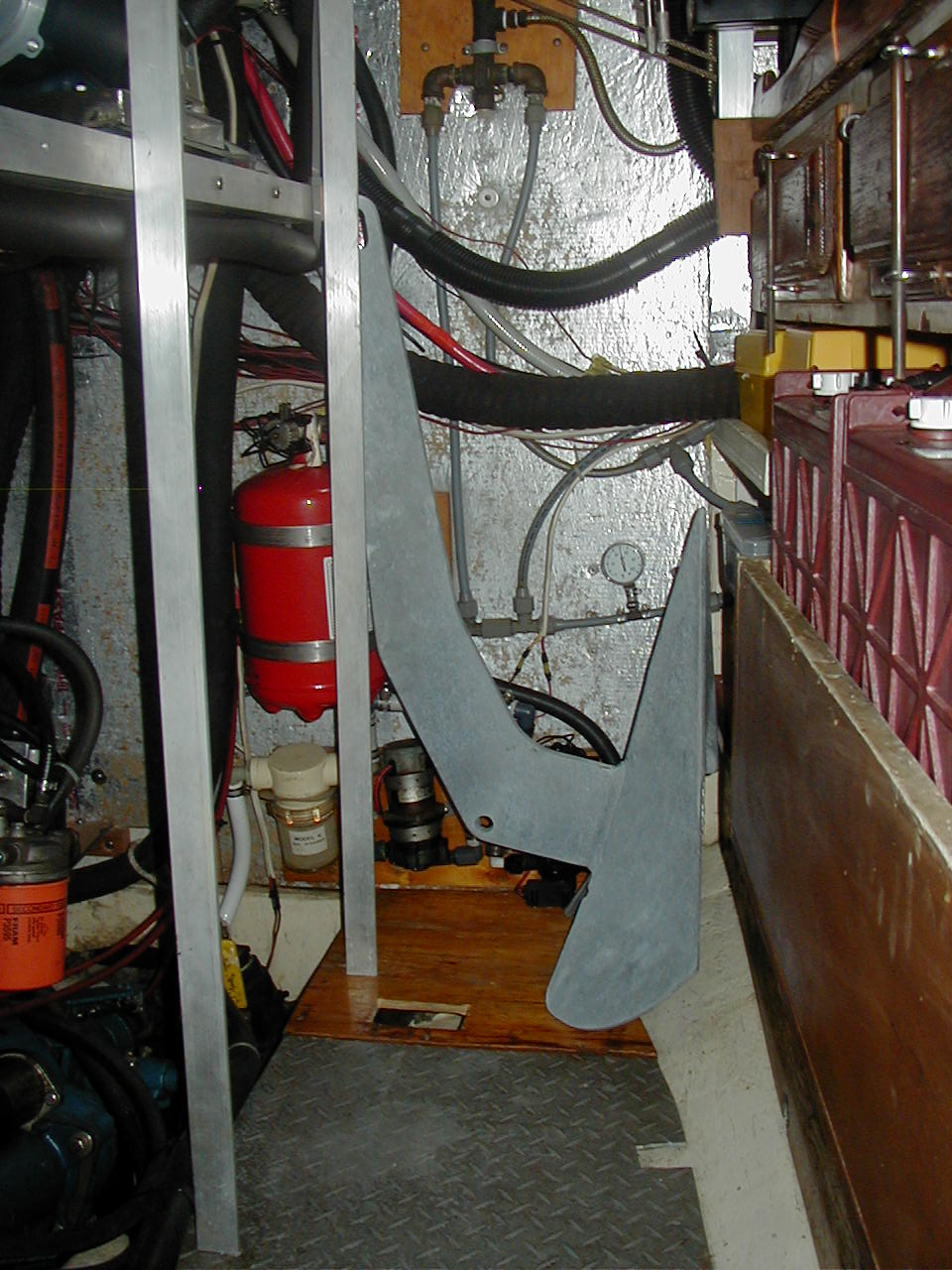 Aft, shelving over engine, auto fire extinguisher, spare Delta 55, old battery locker |
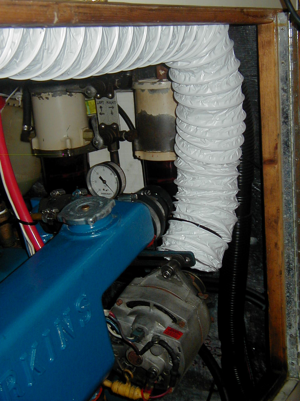 Stbd fwd corner, dual Racor filters, alternator ventilation |
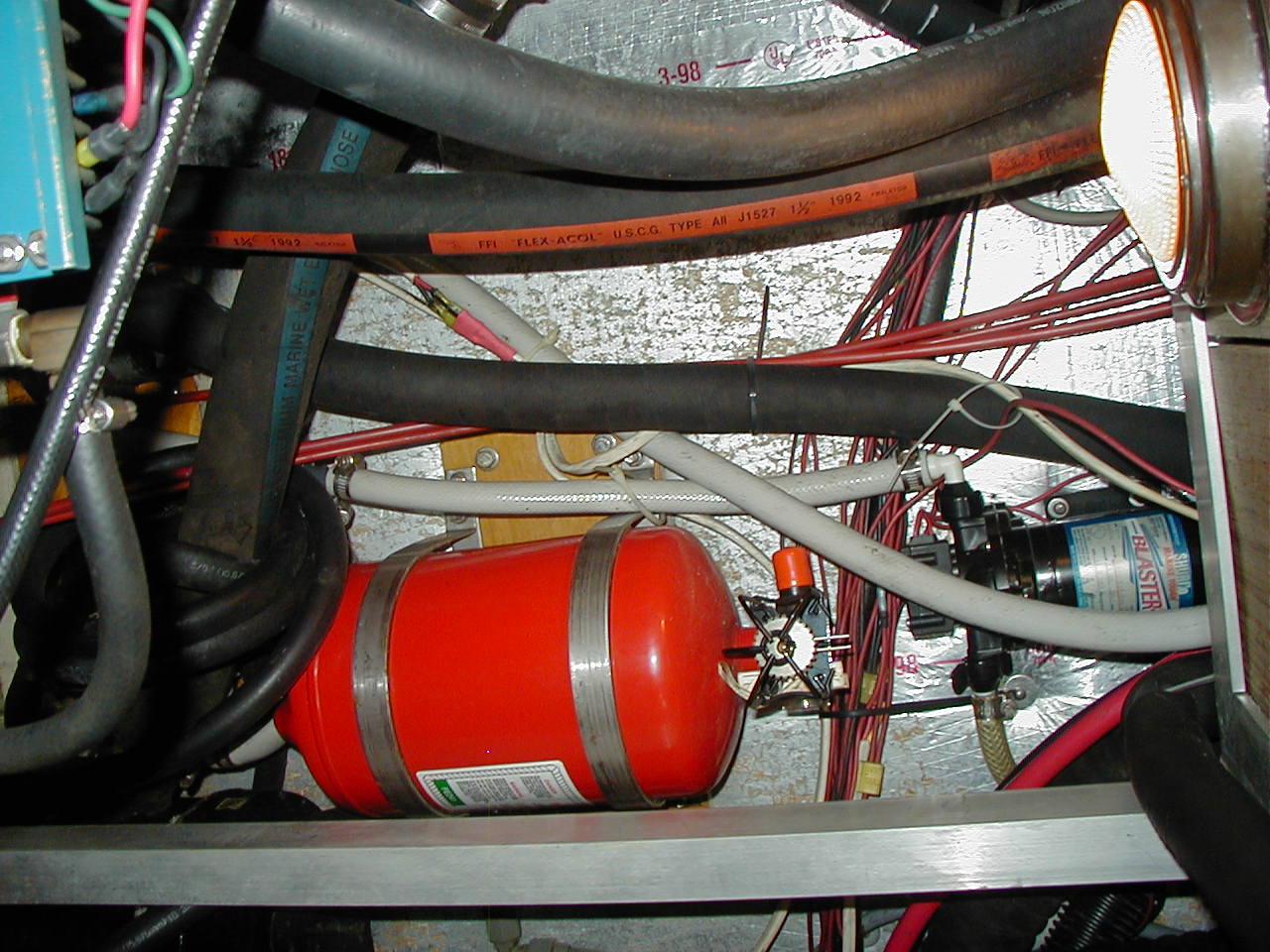 Auto fire extinguisher |
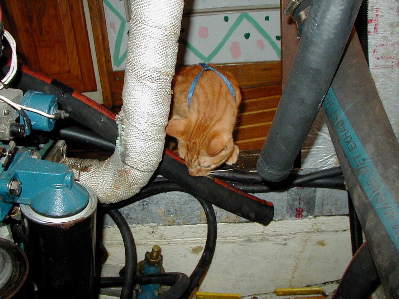 Ship's cat, Radar, inspecting |
 Auto fire extinguisher |
 Top of engine |
 Front of engine |
 Dual Racor filters with vacuum gauge |
 Port side of engine |
|
|
|
|
Water Pump pulley arrangement |
|
|
|
|
|
|
|

Synthetic Engine Oil & Engine Oil Analysis
(Topica Post 1999) I use a lab in Atlanta called Power Trac to do my engine oil analysis (800-394-3669), but there are many others. Just stop by any large diesel dealer and they can sell you a sampling kit consisting of small double plastic bottles for about $12 US.
I take a sample about every 300 hours and send it in via any cruiser going back to the US. After a week or so they will send me the detailed computer printed results via mail, fax or my phone call. It's a great way to keep tabs on what's going on inside the engine.
Most major truck fleets and other multiple diesel users like the US Navy have been doing this for years. Oil analysis is part of what we called trend analysis in the Navy, and it was part of the engineer's work to monitor it.
If you want to do this make sure you get the Amsoil ByPass oil filter to remove contaminants down to 1/2 micron and all moisture from the oil. Otherwise even though your synthetic oil's lubricity may be intact, and it should be for a couple of thousand hours, the oil will get overwhelmed by contaminants and water. In addition to the oil being better for your engine, the main reason I started this was to keep from having to carry the many gallons of oil I would need to change oil every 150 hours as Perkins recommends. Third world oil is of questionable quality and very expensive. I don't understand how most cruisers do this using petroleum oils. The same applies to two cycle oil, so bring gallons with you. You can check out the Amsoil extended oil change program by visiting their website, calling Amsoil headquarters at 715-392-7101 and talking to one of their engineers or get their sales literature from any Amsoil dealer in the yellow pages.
I think it's a great program but have found very few cruising users, maybe because it's not heavily advertised by the marine industry and the engine needs to have low hours when you start the program.
Installing an Auxiliary Fuel Tank and Transfer System
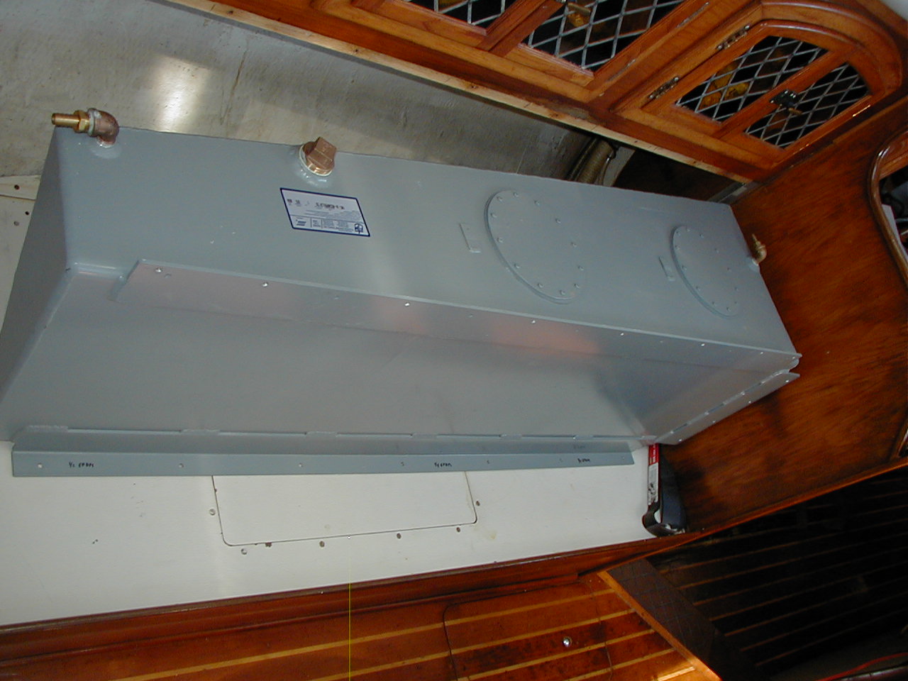
(2005) The new auxiliary fuel tank was constructed of 3/16" aluminum by Florida Marine Tanks in Miami. They do all their own design work using a CAD program which allowed me to review their rendition of the doorskin mockup I had taken them and make changes before they started construction. Since they construct hundreds of tanks a day it was an easy job for them and they were able to include a number of custom features-all for about $300. The tank holds 35 gallons, has two inlets and a vent and two cleanout covers. The top and bottom are securely screwed to the cabinet above and bunk top below while the forward/big end is bolted to a heavy stainless angle fastened to the bunk forward bulkhead.
Fuel can be cycled from the main tank to the auxiliary or vice versa via a new transfer system. The transfer system, consisting of a small 60 GPM Napa fuel pump, a Racor 900 fuel filter, a vacuum gauge and several valves, ensures the fuel is polished whenever it passes through. It can transfer fuel at about 1 GPM. Two sight glasses, one at the new tank and one at the pump, allow monitoring of the fuel level and flow. The tank is kept either totally full or empty to prevent free surface effect and sloshing noises. It is installed on the starboard side so that it can add up to 300 pounds to help offset our normal port list. On the 44 Walkover it would be best mounted on the port side where you can get about 60 gallons and offset the starboard list. Tom Service on Jean Marie, a 44 Walkover, originated the idea for the tank design, placement and transfer system.
|
|
|
|
|
|
|
|
|
|
|
|


A friend had a similar 60 gallon tank done by a custom welding/metalwork shop for about $1500, so be careful when you look for quotes. Big tank manufacturers are a much better bet, because of experience and price, than welding shops. You might also think about installing a polishing/filtering system while you are at it.
Aluminum is the best material to use for fuel tanks. And two tanks are
better than one. That way you can isolate one from the other as backup in
case you contaminate one.
Based on listening to a fellow cruiser that replaced all his fuel and water
tanks (8 I think) on a Westsail 42 with welded seam poly tanks I would not
recommend them for fuel or water. They held fine for several months and then
started leaking. It was a real mess, and eventually he had to tear his whole
interior up, cut off the tops and line the interiors with fiberglass. It
took him months at huge expense (after he had already done this once). The problem is that if the poly welds
aren't perfect, and maybe even if they are, the boat's motion will stress
them until they start to open up. He even had the manufacturer pressure test
them to begin with. And after reading the fine print he discovered that the
poly tanks he used were not recommended for diesel fuel, probably for that
reason. However, even his water tanks started leaking eventually.
There are, however, some poly tanks that are ABYC approved, but they have to be very well supported, like in a bilge area, with bottom and sides supported by the hull. Be real careful with this. Aluminum is a much better way to go, just ask any sail boat manufacturer. And, if an aluminum tank should develop a problem you can easily have it welded anywhere in the world.
Fuel Tank Measuring and Cleaning
My fuel tank, and I think most other quality tanks, have the suction tube
bottom set about 1/2" above the bottom of the tank sump. That way you get to
use almost all the fuel but don't suck up the muck at the very bottom of the
tank. I have used our fuel down to within a half gallon, more than once,
without the engine quitting. A couple of years ago I had an aluminum aux
tank built by Florida Marine Tanks in N Miami, and the engineer told me that
the 1/2" spacing was standard construction procedure for fuel tanks.
It is a good idea to thoroughly clean the inside of your fuel tanks by hand
rag about every 5 years. Fuel polishing is not a good fix if you have dirty
tanks with muck stuck to the sides and bottom. It will invariable get
dislodged at inopportune times, like when at sea in rough weather, and then
clog your filters.
We use a modern plastic housing filter, similar to what West Marine sells,
to filter ALL fuel coming into the tank. These have been tested to be better
than the old and expensive Baja filters. That is the only way to make sure
you are getting clean fuel and won't end up with contaminated fuel at the
bottom of the tank. We also use the Hammond Biobor and Biolube products to
clean and lubricate the fuel. Since the first time I cleaned my fuel tank in
1996 it has been absolutely clean the two times I have opened it since.
I've used a PVC dip stick, marked with permanent marker for my tank for
years. It is simple, reliable, accurate and inexpensive. And it bends under
the Microwave which is mounted over the fuel tank top. Although I have the
original plan tank level scale, I made my own scale by emptying the tank and
then refilling it at the pump marking the stick at 10 gallon intervals. That
way I know it is entirely accurate for my tank. There is a scale for the 44
WOs at this link:
www.sailingwithgrace.blogspot.com
Others mentioned using the Tank Tender System, metal and wooden dipsticks.
If there is nothing mounted above the tank, like in the WOs, a rigid
dipstick would work fine. I know the Tank Tender System is expensive, but
know nothing about the accuracy.
Re filling your tanks, I think you will get tired of filling the tanks twice
every time you need fuel just to test that you got good fuel. Even good US
fuel stations can give you contaminated fuel, and maybe not at the start,
but toward the end of the fill. Just use a good modern fill filter, dual
Racor primarys and treatment, after making sure you have clean tanks to
begin with, and you will be fine. I've not had a problem in 12 years doing
this. The key is you have to use the fill filter and treatment EVERY time
you fill.
(25 Jan 2010 CSYO Post) This note is to make
Perkins owners aware of an adapter that is available for the original engine
secondary fuel filter. This adapter allows you to use modern, commonly
available, spin on fuel filters instead of the original one which requires a
messy change out. It is not for the Racor primary filter.
They are available through Complete Yacht Service in Ft Lauderdale at
954-462-6977, and probably many other diesel dealers. I bought my unit there
11 years ago. See the
Workshop Links
page for their website.
I believe that the two engine filters may be the same and that the adapter
should work for either. Spin on fuel filters are pretty common for diesels.
Just check to be sure the flow rate of the spin on filter you buy matches
what your engine uses. Complete Yacht can help you with this and the
adapter. They may also be sold at other diesel dealers on the internet.
Another option is to replumb the fuel lines on the engine and use a Racor
500 in place of the standard secondary filter. That way you can use a 2
micron element instead of relying on the spin on ratings of around 5 microns
for final filtration. There are a number of differing opinions on this
subject (how much filtration is enough and how to arrange the primary and
secondary filters) so it is worth researching a bit on the internet. You
have to maintain your diesel's maximum fuel flow rate.
We always use a good "Baja" type fuel filter when onloading fuel. That way we
know we are getting good waterless fuel. We use 10 micron filters in the
dual Racor primary filters and a 5 micron secondary spin on filter. We have
a fuel vacuum gage attached to the primary filter housings which will
indicate if the filters need changing. They have never needed changing so I
change them about every 1000 hours. The past two times I have opened up the
tanks for cleaning they have been spotless.
We have not had a fuel problem since just after we bought the boat. That was
in 1996 when the original set up clogged on our way home from the Bahamas in
the Gulfstream. Now I hand clean our tanks every 5 years and use Biobor JF and
Biolube in the fuel.
Fuel Priming System
(Originally a Topica Post 2004)
Like Paul on Peter Rabbit I have had a
gasoline fuel priming bulb in my fuel system between the fuel tank and
the dual Racor filters for 10 years now (same bulb). It is located so I
can fill the filters, bleed the injection pump and operate the bulb all
from the port side of the engine. I can tell you that bleeding the
engine this way is much faster than using the lever on the mechanical
fuel pump on the other side of the engine and does not require two
people to bleed the engine. It is one of those few pieces of equipment on
the boat
that is simple, inexpensive, requires no maintenance and always works.
Still, I carry a backup.
I think it is a good idea to have a backup fuel pump so I have also
installed a small Napa electric pump in the fuel line between the
filters and mechanical pump. It could be used to fill the filters,
bleed the engine or run the engine as long as it works. The only
problem I have had with the mechanical pump over the years is worn
internals causing an external fuel leak. I have no experience with the
electric pump yet but is is electric. Therefore if you do install an
electric pump it might be better to install the pump in parallel rather
than in series with the mechanical pump so you could isolate either
pump.
I also have installed a full transfer system for the main and auxiliary
fuel tanks using a Racor 900 filter, Napa 60 gpm pump and a rather complicated
valve system so the fuel can be filtered going both ways.
Shaft, Stern Tube and Stuffing Box Diameters
(Originally from a Topica Post 7 Sep 07)Just read your email asking for the OD of your shaft
tube. I replaced my hose between the fiberglass tube and bronze log a few
months ago using the 5 ply Buck Algonquin hose from Lewis Marine Supply in
Ft Lauderdale (800-432-2158). Their catalog figure 672 for a 1.5" diameter
shaft shows the correct hose to have a ID of 2.5". Hose number is HO250, 6"
long and cost was about $20. A 5 ply hose is the right stuff, although you
can use lesser hose if you don't mind lesser security and life. I think the
tubes/logs for the WT and WO with 1.5" diameter shafts are the same.
Looking at my 2007 Lewis Marine Catalog under the Buck Algonquin Packing
Box, the kits consist of the stuffing box (hex spud, hex nut, body) and hose
all sized for a specific shaft diameter. The 1.5" diameter shaft calls for a
2.5" ID hose (5 ply with a thick wall) because the fiberglass tube is 2.5"
OD. If you look at the available cutlass bearings that fit inside on the
other end of the tube their available outside diameters for the 1.5" shaft
are 2 and 2-3/8". I use the latter on Soggy Paws. That leaves a 1/16" wall
which is correct.
The next size up box kit is for a 1-3/4" shaft and requires a 3" ID hose and
larger stuffing box. The next size up cutlass bearing is for a 1-5/8" shaft
and has available ODs of 2-1/8" and 2-5/8". Neither of these would fit our
application.
I suspect your measurement of your tube included the fiberglass resin
buildup around the tube aft of the hose. When I measured mine I got the same
thing and it wasn't until I looked in the Lewis catalog that I figured out
what was going on. I did a bit of sanding on the forward half of my tube to
round off the rough edges and get the OD a little closer to the hose ID. I
also used some caulk to help lubricate and seal the joint as I forced the
hose over the end of the tube. Looking at it now the hose is a bit expanded
where it is over the tube from it's relaxed shape. If you use a 1-5/8" ID
hose it will be be too large to fit over the back end of the stuffing box,
and this 5 ply hose doesn't squeeze down easily. For this application tight
is much better than loose. The other option is to use a thinner wall 3 ply
hose which will stretch easier over the tube. I wanted the strength of the 5
ply hose that comes with the Buck Algonquin kit. There was also a bit of
fiberglass dribble under the tube where it went into the hull that I ground
off to get the hose further on the tube. I used strong T-bolt clamps to hold
the hose on to the tube.
If the above doesn't make sense to anyone replacing their stuffing box hose
I recommend you consult with an expert like the people that make the
components, Buck Algonquin Company.
Back to top
The black knob on your binnacle that you pull up to stop the engine is the fuel cut off for the injection pump. I have the same. It is not a compression release. It must be down in order to start the engine as no fuel will get through the injection pump if it is up. If the engine turns over but won't start look at that first. Also, it is worth carrying a spare cable for this and the throttle. They are commonly available Morse cables. You need to know the length and what end fittings you have.
Thermostat Housing Fit
I have a Perkins 4154 NA version and have had the
problem you mention. No matter what you do, it is a tight fit to leave the
SW heat exchanger in place, bolt on the thermostat housing and then fit the
hose between the two.
However, if you use the new blue silicone hose and notch it where it fits
over the inboard thermostat housing stud/nut it will slide on considerably
easier than if you are using black heater hose. Slide the hose on the heat
exchanger first, then bend it to slide over the thermostat housing with the
notch in the hose over the stud and then install the two hose clamps.
It helps if both the heat exchanger and thermostat housing nipples are clean
and smooth and if you apply some Red Silicone Gasket Maker to both. With the
right Perkins thermostat and the blue silicone hose it will be years before
you have to do this job again.